High-Speed Converters: What Are They and How Do They Work?
Acting as the gateway between the “real world” analog domain and digital world of 1s and 0s, data converters have become a critical element of modern signal processing. Over the past three decades, numerous innovations in data conversion not only allowed performance and architecture advances in everything from medical imaging to cellular communications to consumer audio and video, they helped create entirely new applications.
This file type includes high resolution graphics and schematics when applicable.
The continuing expansion of broadband communications and high-performance imaging applications has put a particular emphasis on high-speed data conversion—converters that can handle signals with bandwidths of 10 MHz to more than 1 GHz. A variety of converter architectures are being used to reach these higher speeds, each with special advantages. Moving back and forth between the analog and digital domain at high speeds also presents some special challenges regarding signal integrity—not just for the analog signal, but for clock and data signals, too. Understanding these issues is important when selecting components, and can even impact the choice of overall system architecture.
Faster, Faster, Faster
In many technology domains, we have come to associate technology advances with greater speeds. Data communications, from Ethernet to wireless LAN to cellular, is all about moving bits faster. Microprocessors, digital signal processors, and FPGAs improve substantially through advances in clock rates, primarily enabled by shrinking process lithographies that provide faster-switching, smaller transistors operating at lower power.
Such dynamics have created an environment of exponentially expanding processing power and data bandwidth. These powerful digital engines create an exponentially increasing appetite for signals and data to be “crunched,” from still images, to video, to broadband spectrum, whether wired or wireless. A 100-MHz processor might be able to effectively manipulate signals with 1 to 10 MHz of bandwidth, while processors running at multiple-gigahertz clock rates can handle signals with bandwidths in the hundreds of megahertz.
The greater processing power and speed leads naturally to faster data conversion. Broadband signals expand their bandwidths (often to the spectrum limits set by physics or regulators), and imaging systems look to handle more pixels per second to process higher-resolution images at faster rates. Systems are being redesigned to take advantage of this extreme processing horsepower, including a trend toward parallel processing, which may mean multichannel data converters.
Another important architectural change is a move toward “multicarrier/multichannel,” or even “software-defined” systems. Conventional, “analog-intensive” systems do much of the signal-conditioning work (filtering, amplification, frequency translation) in the analog domain; the signal is “taken digital” after being carefully prepared.
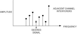
One such example would be an FM radio. A given radio station will be a 200-kHz-wide channel sitting somewhere in the 88- to 108-MHz FM radio band. A conventional receiver will frequency-translate the station of interest to a 10.7-MHz intermediate frequency; filter out all other channels; and amplify the signal to the optimal amplitude for demodulation. A multicarrier architecture digitizes the entire 20-MHz FM band, and digital processing is used to select and recover the radio stations of interest.
While the multicarrier scheme requires much more sophisticated circuitry, it offers some great system advantages (Fig. 1). For instance, the system can recover multiple stations simultaneously, including “side-band” stations. If properly designed, a multicarrier system can even be software-reconfigured to support new standards (e.g., the new “HD radio” stations placed in radio side-bands).
The ultimate extension of this approach is to have a wideband digitizer that can take in all of the bands, and a powerful processor that can recover any sort of signal. This is referred to as a “software-defined radio.” Equivalent architectures exist in other fields—“software-defined instrument,” “software-defined cameras,” etc. One can think of this as the signal-processing equivalent of “virtualization.” The enabling hardware for these sorts of flexible architectures is powerful digital processing, and high-speed, high-performance data conversion.
Bandwidth and Dynamic Range
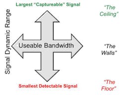
The fundamental dimensions of signal processing, whether analog or digital, are bandwidth and dynamic range (Fig. 2). These two factors determine how much information a system can actually handle. For communications, Claude Shannon’s theorem uses these two dimensions to describe the fundamental theoretical limit of how much information can be carried in a communications channel.
The principles apply across a variety of regimes, though. For an imaging system, the bandwidth determines how many pixels can be processed in a given amount of time, and the dynamic range determines the intensity or color range between the “dimmest” perceptible light source and the pixel’s “saturation” point.
The usable bandwidth of a data converter has a fundamental theoretical limit set by the Nyquist sampling theorem—to represent or handle a signal with bandwidth F, one needs a data converter running at a sample rate of at least 2F (note that this law applies for any sampled data system, be it analog or digital). For practical systems, some amount of oversampling substantially simplifies the system design, so a factor of 2.5X to 3X the signal bandwidth is more typical.
As noted earlier, the continually increasing processing power enhances a system’s ability to handle greater bandwidths, and system trends in cellular telephony, cable systems, wired and wireless LAN, image processing, and instrumentation are moving to more “broadband” systems. In turn, the more voracious appetite for bandwidth demands higher data-converter sample rates.
If the bandwidth dimension is intuitively clear, the dynamic range dimension may be a bit less obvious. In signal processing, the dynamic range represents the spread between the largest signal that can be handled by the system without suturing or clipping, and the smallest signal that can be effectively captured.
One can consider two types of dynamic range. The first, “floating-point” dynamic range, may be realized with a programmable gain amplifier (PGA) in front of a low-resolution analog-to-digital converter (ADC); imagine a 4-bit PGA in front of an 8-bit converter for 12 bits of floating-point dynamic range. With the gain set low, this arrangement can capture large signals without over-ranging the converter. When the signal is very small, the PGA can be set for high gain to amplify the signal above the converter’s “noise floor.” The signal could be a strong or weak radio station, or a bright or dim pixel in an imaging system. Such floating-point dynamic range can be very effective for conventional signal-processing architectures that are trying to recover only one signal at a time.
The second, “instantaneous” dynamic range, is more powerful. In this arrangement, the system has sufficient dynamic range to simultaneously capture the large signal without clipping and still recover the small signal. In this case, a 14-bit converter may be required.
This principle applies across a number of applications—recovering both a strong and weak radio station or cell-phone call signal, or a very bright and very dim section of one image. As systems want to move to more sophisticated signal-processing algorithms, the tendency is toward needing more dynamic range. This allows the system to handle more signals. If all signals are the same strength, and twice as many signals need processing, it would require an extra 3 dB of dynamic range (all other things being equal). Perhaps more important, as noted previously, if the system needs to simultaneously handle both strong and weak signals simultaneously, the increase in dynamic-range requirements can be much more dramatic.
Different Measures For Dynamic Range
In digital signal processing, the key parameter for dynamic range is the number of bits in the representation of the signal, or word length. Simply, a 32-bit processor has more dynamic range than a 16-bit processor. Signals that are too large are “clipped”—a highly nonlinear operation that destroys the integrity of most signals. Signals that are too small (less than 1 LSB in amplitude) become undetectable, and are lost. This “finite resolution” is often referred to as quantization error, or quantization noise, and can be an important factor in establishing the “floor” of detectability.
Quantization noise is also a factor in mixed-signal systems. However, a number of factors can determine the usable dynamic range in data converters, each with its own specification:
• Signal-to-noise ratio (SNR): The ratio of the full scale of the converter to the total noise in the band. This noise could come from quantization noise (as described above), thermal noise (present in all real world systems), or other error terms (such as jitter).
• Static nonlinearity: Differential nonlinearity (DNL), and integral nonlinearity (INL) are measures of the non-idealities of the dc transfer function from input to output of the data converter (DNL often established the dynamic range of an imaging system).
• Total harmonic distortion: Static and dynamic nonlinearities produce harmonic tones, which can effectively mask other signals. THD frequently limits the effective dynamic range of audio systems.
• Spurious-free dynamic range (SFDR): It considers the highest spectral “spur,” whether it be a 2nd or 3rd harmonic, clock feedthrough, or even 60-Hz “hum,” compared to the input signal. Since the spectral tones, or spurs, can mask small signals, SFDR is a good representation of usable dynamic range in many communications systems.
Other specifications are available. In fact, each application may have its own effective description of dynamic range. The data converter’s resolution is a good “first proxy” for its dynamic range, but choosing the right spec as the true determination is very important. The key principle is that more is better, and while many systems immediately recognize the need for greater bandwidth in their signal processing, the implications for dynamic range may be less obvious, but even more demanding.
It’s worth noting that while bandwidth and dynamic range are the two primary dimensions of signal processing, it’s useful to think about a third dimension of “efficiency.” This helps us get at the question of “how much will the extra performance cost me.” We can think of cost in terms of purchase price, but a more “technically pure” way of weight cost for data converters and other electronic signal processing is in terms of power consumption. Higher-performance systems—those with more bandwidth or more dynamic range—tend to consume more power. Further technology advances look to push bandwidth and dynamic range up, and power consumption down.
Key Applications
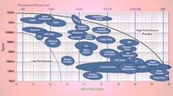
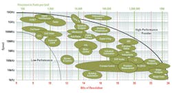
As just described, each application will have different requirements in terms of these “fundamental signal dimensions,” and within a given application there can be a wide range of performance. For example, consider a 1-Mpixel camera versus a 10-Mpixel version. Figure 3 provides a representative illustration of the bandwidth and dynamic range typically required in different applications. The upper half of the chart will often be characterized as “high speed,” meaning converters with sampling rates of 25 MHz and greater that can effectively handle bandwidths of 10 MHz or more.
It’s worth noting that this “applications picture” isn’t static—existing applications can exploit new, higher-performance technologies to increase their capabilities, such as high-definition camcorders or higher-resolution “3D” ultrasound machines. Entirely new applications also emerge each year, many of them at the “outer edge” of the performance frontier enabled by new combinations of high speed and high resolution. This creates an “expanding edge” of converter performance, like a ripple in a pond.
Another important point is that most applications have power-consumption concerns. For portable/battery-powered applications, power consumption may be the primary technical constraint, but even line-powered systems are finding that the power consumption of the signal-processing elements (be they analog or digital) ultimately limit how much the system can accomplish in a given physical area.
Tech Trends and Innovation—How We’re Getting There
Given this “applications pull” for increasing high-speed data-converter performance, the industry responded with further technological advances. The “technology push” for advanced high-speed data converters comes from several factors:
• Process technologies: Moore’s Law and data converters—the semiconductor industry has a remarkable track record for continuously advancing digital processing horsepower, substantially driven by advances in wafer processing to ever-finer lithography. Deep-submicron CMOS transistors have much greater switching speeds than their predecessors, enabling controllers, digital processors, and FPGAs to clock at multi-gigahertz speeds.
Mixed-signal circuits like data converters can also take advantage of these lithography advances and “ride Moore’s Law” to higher speeds. However, for mixed-signal circuits, there is a “penalty” in that the more advanced lithography processes tend to operate at increasingly lower supply voltages. This results in smaller signal swings in analog circuits, making it more difficult to maintain analog signals above the thermal noise floor—one gets increased speed at the price of reduced dynamic range.
• Advanced architectures (this is not your grandmother’s data converter): In concert with the semiconductor process advances are the several waves of innovation in high-speed data-converter architectures over the last 20 years, leading to greater bandwidths and greater dynamic range with remarkable power efficiency. A variety of approaches are traditionally used for high-speed ADCs, including flash, folding, interleaved, and pipeline, which continue to be very popular. They have been joined by architectures more traditionally associated with lower-speed applications, including successive approximation register (SAR) and delta sigma, which have been adapted to high-speed use.
Each architecture offers its own set of advantages and disadvantages. Certain applications will tend to find “favorite” architectures based on these tradeoffs. For high-speed digital-to-analog converters (DACs), the architecture of choice tends to be switched-current-mode structures. There are many variants of these structures, though. Switched capacitor approaches have steadily seen increases in speed, and are still particularly popular in some embedded high-speed applications.
• “Digitally assisted” approaches: In addition to process and architecture, circuit techniques for high-speed data converters have undergone quite a bit of innovation over the years. Decades-old calibration approaches have been critically important in compensating the element mismatch inherent in integrated circuits and allowing circuits to reach to higher dynamic range. Calibration has moved beyond the domain of correcting static errors, and is increasingly being used to compensate dynamic nonlinearities, including settling errors and harmonic distortion.
Innovations in all of these areas, taken as a whole, have substantially advanced the state of the art in high-speed data conversion.
Making It Work
Implementing a broadband mixed-signal system takes more than just the right data converter—these systems can place stringent demands on other portions of the signal chain. Again, the challenge is to realize good dynamic range over a wide bandwidth—getting more signal into and out of the digital domain to take advantage of the processing power there.
• Broadband signal conditioning: In conventional “single-carrier” systems, signal conditioning is about removing unwanted signals as quickly as possible, and then amplifying the desired signals. This often involves selective filtering, and narrowband systems that are “tuned” to the signals of interest. These tuned circuits can be very effective in realizing gain, and in some cases, frequency-planning techniques help ensure that harmonics or other spurs fall “out of band.” Broadband systems can’t use these narrowband techniques, and it can be quite challenging to realize broadband amplification in these systems.
• Data interfaces: Conventional CMOS interfaces can’t support data rates much greater than 100 MHz, and low-voltage differential swing (LVDS) data interfaces run up to 800 MHz to 1 GHz. For larger data rates, one can shift to multiple-bus interfaces, or move to SERDES interfaces. Contemporary data converters employ SERDES interfaces at up to 12.5 Gsamples/s (as specified in the JESD204B standard)—multiple data lanes can be used to support different combinations of resolution and speed in the converter interface. These interfaces often are quite sophisticated in their own right.
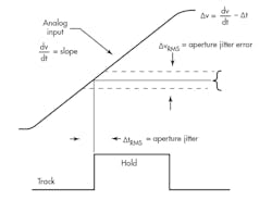
• Clock Interface: Processing high-speed signals can also be very demanding regarding the quality of the system’s clock. Jitter/error in the time domain translates into “noise” or errors in the signal, as illustrated in the signal (Fig. 4). When processing signals greater than 100 MHz, clock jitter or phase noise can become a limiting factor in the converter’s usable dynamic range. “Digital-quality” clocks may be insufficient for these sorts of systems, and thus may require high-performance clocks.
This file type includes high resolution graphics and schematics when applicable.
To sum up, the trend to broader-band signals and “software-defined” systems continues to accelerate, In response, the industry keeps coming up with innovative new ways to build “better, faster” data converters, pushing the dimensions of bandwidth, dynamic range, and power efficiency to new benchmarks.
David (“Dave”) Robertson is vice president of Analog Technology for Analog Devices. He holds 16 patents on converter and mixed signal circuits, has participated in two “best panel” International Solid State Circuits Conference evening panel sessions, and was co-author of the paper that received the IEEE Journal of Solid State Circuits 1997 Best Paper Award. He served on the Technical Program Committee for the International Solid States Circuits Conference (ISSCC) from 2000 to 2008 and has served as chair of the Analog and Data Converter subcommittees from 2002 through 2008. He has a BA and BE from Dartmouth College with dual majors in economics and electrical engineering. He can be reached at [email protected].
