Microcontroller Generates Analog Gaussian Waveform Without Need for a DAC
This file type includes high resolution graphics and schematics when applicable.
Laboratory data often appears as Gaussian curves, and today's laboratory data-acquisition software is designed to analyze these data to determine such things as peak location, amplitude, area, and width. A good test signal is useful in developing such software, and it is best when the test signal resembles actual analog data including noise.
Many years ago, while I was still a student, a professor and I built a few Gaussian-curve generators for students to use in a teaching laboratory. Since those were the days before inexpensive microcontrollers, you can imagine the complexity of such circuitry. Fast forward a few decades, and I needed a Gaussian-curve generator for a software-development project. Of course, it's always possible to generate an arbitrary waveform with a microcontroller and a digital-to-analog converter (DAC). Although inexpensive microcontrollers contain high-resolution analog-to-digital converters (ADCs), DACs are peripheral components.
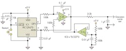
The simple microcontroller circuit (Fig. 1) generates an analog Gaussian curve without needing a DAC. The key to the design is that most microcontrollers allow their I/O pins to be dynamically reconfigured to function as either a high-impedance input, or as an output. The analog core of the circuit is an operational amplifier integrator (IC2b) whose reference voltage is set at half the supply voltage by the other half (IC2a) of a dual package.
When microcontroller output (GP1) is in its high-impedance state, integrator IC2b neither charges nor discharges, so the output voltage is constant. When the output voltage as read by the microcontroller's analog input (AN0) shows that more output voltage is required, the software sets GP1 to its low-voltage state, so the integrator will charge.
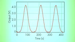
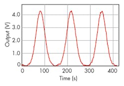
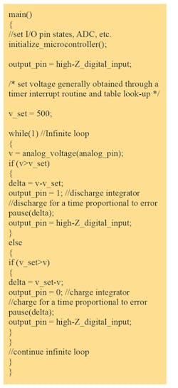
When too high a voltage is sensed, GP1 is set to its high-voltage state, and the integrator will discharge. The software, shown in the pseudocode listing below, is designed so that this servo loop is damped to prevent excessive "seeking" around the setpoint voltage, as is shown in the output (Fig. 2).
Rail-to-rail op amps, like the one used in this circuit, don't function well with signals near the rails, so getting a true zero-voltage signal isn't possible with a unipolar supply. Bench measurements on the circuit show a minimum voltage of about 30 mV when driving a high-impedance load. Also, this approach to voltage generation won't work for rapidly-changing signals. For the 4-MHz processor used, two updates per second are about the limit.
The internal memory of the PIC 12F675 microprocessor is limited to just 128 8-bit bytes, which allows for just a small lookup table. By using a linear interpolation of adjacent data points, you can double the temporal resolution, and since the curve is symmetric, the temporal resolution can be doubled again.


