Capacitive Sensors: An Attractive Option for Contactless Sensing
Download this article in .PDF format
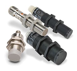
Capacitive sensing is a contactless-sensing technique with numerous applications, ranging from proximity sensing (Fig. 1), gesture recognition, automotive rain sensors, and remote liquid-level sensing to material handling and high-resolution metal profiling. It's even used to make music, as we'll discover.
1. Capacitive proximity sensors are available in rugged housings for industrial applications. (Courtesy of Automation Direct)
The sensor in a capacitive-sensing system can be any metal or conductor, allowing for highly flexible system design. Due to their low power consumption, low cost, and high resolution, capacitive sensors are replacing inductive, optical, and ultrasonic technologies in many applications.
Although a capacitive sensor can be as simple as a dedicated area on a printed-circuit board, many other options exist for system designers, including devices with integrated electronics.
Capacitive sensing isn’t the same as capacitive touch, a related technology that's optimized to perform a digital switch function. A capacitive-touch system often uses many channels in a row and column arrangement; think about the touchscreen on your cell phone of tablet. It requires contact to operate and works over a short range—a few millimeters at most. Sensing, Not Touch
In contrast, a capacitive sensor is an analog system that operates at distances of up to 70 cm. It has much greater sensitivity and precision since it must resolve changes in capacitance of a few picofarads.
Principles of Capacitive Sensing
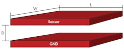
The capacitance of a system represents its ability to store an electrical charge and is a fundamental electrical property. A capacitor is a component used to store electrical energy in an electrical field; the simplest model consists of two electrical conductors or plates separated by an insulating dielectric (Fig. 2).
For the capacitor shown in Fig. 2, the capacitance in farads is given by:
where:
A = the area of the plates (W x L)
d = the plate separation in meters
εr = the dielectric constant of the material between the plates
ε0 = the permittivity of free space (8.85 x 10⁻¹² F/m)
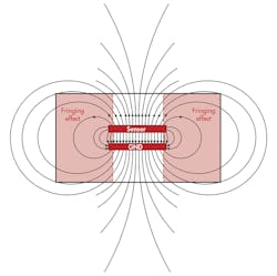
When the sensor plate is charged, it creates an electric field (Fig. 3).
Turning a Capacitor into a Sensor
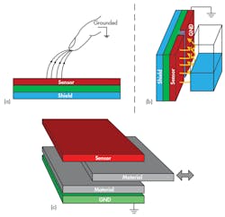
How do we turn this device into a capacitive sensor? Figure 4 shows three options.
4. Three topologies for capacitive sensors: proximity sensor using a finger as the ground plate (a), liquid-level sensing with parallel sensor and ground (b), and material detection and analysis (c). (Courtesy of TI)
A proximity sensor is formed by constructing an isolated sensor plate out of a conductive area on a circuit board and charging it. Then a capacitor will be formed any time a grounded, conductive object, or an object with a dielectric constant different from air, comes close to the sensor plate. A finger qualifies because the human body is essentially at ground potential.
The capacitance increases as the finger approaches the sensor. Even though the variation is nonlinear, a detectable difference is sufficient for proximity detection.
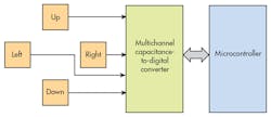
To expand this into a gesture sensor, we can use multiple independent sensors for up/down and left/right detection (Fig. 5). As the finger moves over the sensors, it changes the capacitance of all four sensors. A multichannel detector reads all four values; then software can calculate speed and direction based on the difference in readings.
5. Decoding gestures requires four capacitive proximity sensors and a multichannel converter. (Provided by the author)
In many applications, such as chemical storage, industrial process control, or commercial washers, it's necessary to sense the level of a liquid. In this case, the sensor and ground plates can be situated next to each other, as shown in Fig. 4b, resulting in a configuration with high sensitivity along the vertical access.
As the liquid level varies, it changes the dielectric value and hence the capacitance. This sensor configuration makes use of fringe field lines; thus, the capacitance calculations are more complicated than in the case of a simple plate.
A sensor for materials analysis consists of the basic plate topology shown in Fig. 4c with the material to be analyzed—paper, for example—changing the dielectric constant between the plates as it's added or removed. The unloaded sensor has an air dielectric and serves as the reference capacitance. Then the capacitance increases as paper or other material is inserted between the plates.
These aren't the only sensor configurations, of course. Other options include multiple sensor and ground arrangements, either separate or arranged in an interlocking comb pattern that requires a large sensor area and high sensitivity.
Shielding and Capacitive Sensing
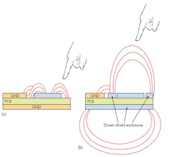
One issue with capacitive proximity sensing is that the field lines will flow from the sensor plate to any nearby ground potential. Ideally, the target being sensed will be the dominant influence. However, numerous parasitics (e.g., ground planes or ground traces) will usually steal away charge and reduce the sensor's sensitivity and detection distance. This is a particular problem in noise-sensitive environments, since ground planes are a standard design solution.
6. The effects of PCB parasitics (a) on sensor performance can be reduced by driven shield electrodes (b). Shield drivers are included in capacitive-sensor interface devices and specialized microcontrollers. (Courtesy of TI)
Adding an active shield can help reduce parasitic and environmental interference, and allow the sensor to operate at full capability (Fig. 6). A well-designed active shield will also focus the sensor output and direct it in the desired direction.
The shield driver is an active output that’s driven at the same voltage as the sensor input. Therefore, no difference in potential exists between the shield and sensor input. Any external interference will couple to the shield electrode with minimal interaction with the sensor electrode.
Capacitive Sensor Interface Block Diagram
A specialized analog front end converts the signal from the capacitive sensor into a digital value suitable for further processing (Fig. 7). It periodically samples the sensor output and provides an excitation signal to charge the sensor plate. The sensor output sampling rate is relatively slow—less than 500 samples per second—but high-resolution analog-to-digital conversion is needed to capture small differences in capacitance. A 16-bit sigma-delta ADC provides a good compromise between speed, resolution, and low power consumption.
7. In a capacitive-sensing device, the excitation step waveform charges the sensor electrode. Subsequently, the charge is transferred to a sample-and-hold circuit and measured by an analog-to-digital converter. (Courtesy of TI)
A multichannel device can perform differential measurements to obtain an accurate representation of the capacitance difference between two sensors. For example, if environmental factors cause variations in capacitance, one channel can be dedicated to an environmental sensor that monitors changes in dielectric caused by temperature, humidity, material type, stress on the material, and so on. A differential measurement can null out changes due to these variables.
For certain applications, ratiometric measurements are also valuable. In liquid sensing, one channel measures capacitance related to the liquid level; a second channel is for the reference sensor, which measures the capacitance of the zero level. Since the level capacitance is proportional to liquid height, a ratiometric measurement measures the ratio or difference between the level sensor and reference.
LC-Based Capacitive Sensing
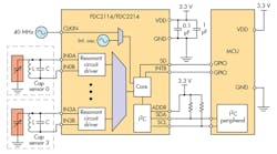
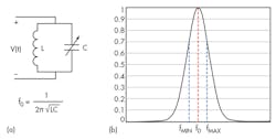
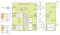
One of the issues with capacitive sensing is the coupling in of stray noise. Modifying the sensor to include a frequency-sensitive component is a useful way to increase noise immunity. In addition to the variable capacitor element, an additional capacitor and inductor is added to the sensor to form a resonant inductive tank circuit (Fig. 8).
Although the architecture of the LC tank is simple, it has a couple of major advantages when integrated as part of a capacitive sensor (Fig. 9). First, due to its inherent narrowband characteristics, an LC resonator provides excellent immunity to electromagnetic interference (EMI). Second, if noise sources are known to exist at certain frequencies, shifting the sensor’s operating frequency can filter out these noise sources without using external circuitry. This will help increase system sensitivity and reduce complexity.
Using this approach, a change in the capacitance of the LC circuit is seen as a shift in the resonant frequency. TI applied this principle in its FDC2214, a capacitance-to-digital converter that measures the oscillation frequency of an LC resonator-based sensor. The device outputs a digital value that’s proportional to frequency. This frequency measurement can be converted to an equivalent capacitance by a downstream MCU.
Time for a Break!
And now for something completely different... in addition to its many industrial uses, it's even possible to use capacitive sensing to produce music. The theremin, invented in 1919 by Leon Theremin, can produce sounds over a seven-octave range (Fig. 10). Each of performer's hands acts to vary the capacitance in an LC circuit, controlling volume and pitch via two independent heterodyne circuits.
10. The theremin uses capacitive sensing to produce eerily beautiful music. The performer's left hand controls pitch; the right controls volume. (Courtesy of TED.com)
In action, the performer looks like she's simply waving her hands around next to two radio antennas, but the sounds are reminiscent of voice, violin, and even bass. Here's a video of thereminist Pamelia Kurstin explaining the technique and performing two old jazz tunes. As you can imagine, making music in this way requires precise control of hand and arm position. An unexpected sneeze or cough can be disastrous!
Conclusion
Capacitive sensing is a flexible technology that’s becoming increasingly popular. Constructing a sensor can be as simple as adding a conductive area to a printed-circuit board, and low-cost integrated interface chips are readily available. Its low cost and low power consumption make it an ideal choice for a wide range of consumer and industrial applications.
Looking for parts? Go to SourceESB.
