Boost Reverse-Battery Protection for Automotive Electronic Control Units
This file type includes high-resolution graphics and schematics when applicable.
Modern passenger cars increasingly depend on electronic systems, both to satisfy mandatory legal requirements on aspects such as safety and efficiency, and to present attractive features for buyers. The world’s automotive original equipment manufacturers (OEMs) are expected to be fitting almost $280 billion of electronics in vehicles by 2020.
The number of electronic control units (ECUs) associated with engine control, braking control, transmission control, battery management, door equipment, and others can range from about 50 to more than 100, depending on the type of vehicle.
To ensure reliability, the ECUs must be protected against threats such as reverse-battery connection and electrical surges that may be conducted or coupled through the vehicle’s wiring. Reverse-battery connection can occur by accident when reconnecting the battery after electrical maintenance, or when the battery is replaced at its end of life, despite measures such as color coding and mechanical polarization of the battery terminals and connectors. The vehicle’s ECUs must be able to survive this type of error.
To protect the ECU against the effects of reverse connection, designers can choose from a range of approaches, from simple standard devices to small application-specific ICs. However, each comes with its own advantages and drawbacks. To choose an approach that best meets the demands of a given application, designers need to consider the effects on cost, energy efficiency, bill of materials, electromagnetic compatibility, and resilience to applicable ISO 7637 test pulses. The latter are a series of pulses designed to test compatibility of equipment installed in vehicles to conduct electrical transients.
Reverse-Battery Protection Choices
The simplest means of protecting against reverse-battery connection is to insert a rectifier diode in series with the ECU load so that current can pass only when the battery is correctly connected. Since no control signal is required, circuit complexity and component count are low. On the other hand, the diode dissipates energy the entire time the ECU is powered, owing to its forward voltage (VF), which can cause significant losses in high-power applications.
These losses can be mitigated by specifying a low-VF device, such as a Schottky diode, instead of a standard rectifier. However, the reverse-leakage characteristic of the Schottky diode is particularly dependent on temperature. This results in increased energy losses and leaves the device vulnerable to thermal runaway if high reverse power is applied under high-temperature conditions.
An alternative is to insert a MOSFET in the high-side supply to the ECU, connecting the gate so that the device is turned on only when the battery polarity is correct. Since the MOSFET on-resistance (RDS(ON)) is typically only a few milliohms, I2R power losses are low compared to the loss incurred due to the diode VF. In addition, reverse-blocking performance is more robust than that of a Schottky diode. An N- or P-channel MOSFET may be used, provided the device’s drain-source body diode is oriented to conduct current flowing in the correct direction into the ECU.
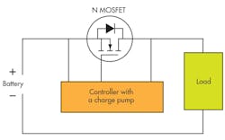
High-side reverse-battery protection can be realized with either an N- or P-channel MOSFET. An N-channel device offers the lowest power-loss topology by virtue of its low RDS(ON). However, a gate voltage greater than the battery voltage is needed to turn the MOSFET on. That requires a charge pump (Fig. 1), which increases circuit complexity and component cost, and can introduce EMI challenges. Although inserting the N-channel MOSFET in the low-side would eliminate the need for a charge pump, it would also introduce a ground shift that’s not acceptable for sensitive automotive systems.
A comparably sized P-channel MOSFET will have a higher RDS(ON) and hence higher power losses. However, it can be implemented with simpler drive circuitry comprising a Zener diode and a resistor.
Super Barrier Rectifier
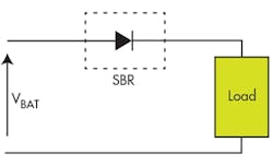
An alternative to these approaches is the Super Barrier Rectifier (SBR). This proprietary rectifier technology from Diodes Inc. combines the simplicity and robustness of a conventional diode with the low forward voltage of a Schottky diode in order to enhance performance. Figure 2 shows how the SBR is inserted in the high-side supply to the ECU, in much the same way as a conventional diode.
Unlike the typical Schottky device, the SBR uses a MOS channel to create a low potential barrier for majority carriers, which results in a combination of low VF with high reliability. At the same time, the SBR has lower reverse leakage, which remains stable even at high temperatures. This helps minimize energy losses and avoids the risk of thermal runaway that’s associated with Schottky diodes. Moreover, freedom from Schottky junctions also ensures higher surge tolerance. And, unlike protection circuitry using an N-channel MOSFET, EMI concerns are eliminated because there’s no charge pump.
Protecting Against Transients and Surges
Although designed to prevent current flow due to reverse-battery connection, the protection device can itself be exposed to potentially damaging transients. Numerous types of switching transients may give rise to pulses of short duration. However, the most dangerous high-energy pulses are caused by events such as sudden disconnection of the supply when powering an inductive load, or by load dump—when the battery is disconnected while charging from the alternator, resulting in a severe positive pulse.
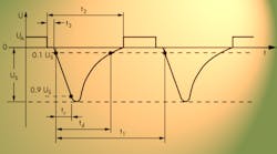
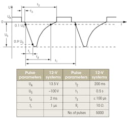
The ISO 7637 standard provides a series of electrical-transient compatibility tests that an ECU must pass. The tests are designed to simulate the various “worst-case” transients that can occur in vehicle. Of these, Pulse 1 and Pulse 5a simulate the harsh pulses due to supply disconnection and load dump, respectively, which represent the greatest threats to the ECU reverse-battery protection devices.
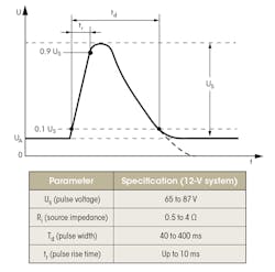
Figure 3 illustrates the ISO Pulse 1 test conditions. The reverse-battery protection device must be able to survive this pulse. If a Schottky diode is used, the device must have high blocking voltage to ensure survivability. The tradeoff is that devices with higher voltage ratings also have higher VF, leading to greater losses.
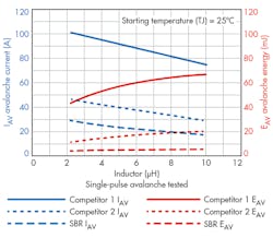
MOSFETs and SBRs, on the other hand, have well-defined avalanche characteristics that allow for the use of a lower voltage rating, which increases efficiency in normal operation. An SBR typically has avalanche capability between three and 10 times better than that of a Schottky device of similar voltage rating (Fig. 4). With careful design, a MOSFET-based solution can deliver avalanche ruggedness similar to that of an SBR.
The ISO 7637 Pulse 5a (Fig. 5), which simulates a load-dump condition, is the most severe positive pulse the device will experience. To ensure the chosen protection device is able to survive this test, designers need information about its forward-surge-current capability. This information is provided in the datasheets for AEC-Q101-qualified SBRs.
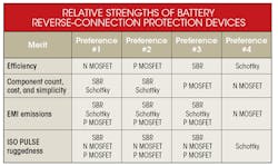
By evaluating the key characteristics of a reverse-battery protection device, including efficiency, cost, reliability, and electromagnetic compatibility, it’s possible to compare the strengths of the SBR against existing Schottky and MOSFET technologies. The table summarizes the analysis. This reference can help designers select the optimum approach based on application priorities.
Conclusion
A number of approaches are viable when implementing required battery reverse-polarity protection for automotive ECUs. Designers need to consider factors like ECU power consumption and cost to achieve an optimal combination of efficiency, circuit complexity, electromagnetic compatibility, and ruggedness. The Super Barrier Rectifier, which has been developed for high-power, high-temperature applications such as automotive, provides a competitively priced alternative to the Schottky diode. It can deliver greater efficiency and reliability in situations where low cost, low complexity, and freedom from EMI issues are priorities.
Looking for parts? Go to SourceESB.
This file type includes high-resolution graphics and schematics when applicable.
