This file type includes high-resolution graphics and schematics when applicable.
It's fairly easy to add features to operating systems such as Linux when used in embedded systems. However, one of the functions needed in these systems is sufficient time to safely shut them down upon removal of system power. Not allowing for a proper shutdown can lead to data corruption to the point where the system may not reboot when power is reapplied.
One way to provide time for the system to shut down is to design-in supercapacitors (sometimes called ultracapacitors) as a backup power system. In this way, power to the processor can be maintained for up to several minutes after the mains power is cut, to allow time to write any open files to disk and properly shut down any remaining processes.
Several major vendors make ICs that control the charging and discharging of the supercapacitors. Since the voltage on these capacitors varies as they are charged and discharged, the vendors also offer dc-dc converters that convert the varying voltage to a stable voltage that’s suitable for powering the rest of the system. These off-the-shelf circuits continue to provide a stable voltage until the supercapacitor voltage drops below a certain level. However, when the voltage gets to this level, commercial circuit functions are inadequate.
The voltage that’s measured at the capacitor terminal is a function of the stored charge and the voltage drop due to its internal resistance. When the capacitor voltage falls below the shutoff threshold, the dc-dc converter and other loads are removed. The voltage drop that was created by the load current across the internal resistance is also removed, which increases the voltage at the capacitor terminals.
If the current draw on the system was high enough, the result of removing it can be that the capacitor voltage again becomes high enough to turn the dc-dc circuit back on. The load is reattached, the voltage drops, and the dc-dc circuit turns off again. This off/on/off cycling repeats itself and the result is continuous oscillations of the system's power network.
To prevent this power oscillation, a circuit with a controllable amount of hysteresis was needed so that it will not oscillate, even during worst-case load conditions. In addition, this circuit had to work from 0 to 5 V. Several op-amp circuits were considered for this application, but even the low-voltage op amps have undefined behavior when their VCC rails are brought from 0 V to VMIN.
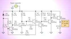
The figure shows a circuit that can address this problem. The main circuit's power is provided by the supercapacitor voltage. As the capacitors charge from 0 V, very little current flows through Zener diode D1. As the capacitor voltage reaches approximately 4.3 V, current starts to flow though D1 and into R1. Once 150 μA of current flows and generates about 0.7 V across R1, Q1 will start to turn on. Q2 would have been turned on up to this point, but when Q1 starts to conduct through R3, it will pull the base of Q2 low and turn it off. This pulls the base of Q3 high, allowing it to start conducting current.
The current from Q3 is directed through R8. Some of this current will flow in Q1 and some will flow through R1. Therefore, rather than the voltage across R1 being dictated solely by the current through D1, it will now increase to account for the current from Q3. It’s this additional current that provides the needed hysteresis and causes Q1 to turn off at a lower supply voltage compared to what it turned on beforehand.
Note that the voltage at the collector of Q2 will turn Q4 on, which turns Q5 off, and subsequently turns Q6 on. The voltage drop across R13 provides a signal to the DC-DC circuit that the voltage on the supercapacitors is high enough that it should turn on.
If the mains power is now removed and the system starts to draw current from the supercapacitors, the main voltage rail for this circuit will start to drop as well. However, since the voltage at R1 is due to the sum of the currents through D1 and Q3, the voltage has to fall to around 2.3 V before Q1 is turned off. This action will turn Q2 on, Q4 off, Q5 on, and finally turn Q6 off. When that happens, no current will flow through R13 and this will signal the dc-dc circuit that it should turn off as well.
Once the load from the dc-dc circuit is removed, the main voltage rail will increase somewhat. However, as long as it doesn’t increase by more than 2 V, the circuit will not turn on again, thus preventing power-line oscillation. Different turn-on and turnoff voltages can be realized by replacing D1 and by changing the value of R8.
Rick Bosma is an electronics engineer in charge of product design at Dairy Cheq Inc. (Waterloo, Ontario, Canada). He has an Electronics Technologist Diploma from RCC College of Technology (Toronto) and a Bachelor of Engineering degree in electronics from Lakehead University (Thunder Bay). He spent seven years in the Product Engineering group at Honda Motor Company before joining Dairy Cheq in 2009.
This file type includes high-resolution graphics and schematics when applicable.


