Hybrid Switching/Linear Method Yields LED-Current Controller with Wide Dimming Ratio
This file type includes high-resolution graphics and schematics when applicable.
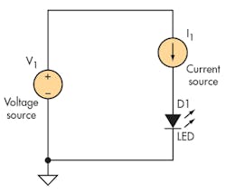
Many applications for LED illumination require wide dimming ratios, which can be easily done using an adjustable current source (Fig. 1).
1. LEDs are current-driven, rather than voltage-driven, devices, and their output intensity is related to the current levelâbut not linearly.
The current source can be adjusted over a large LED current range using several different techniques. The primary problem with this technique is that the power dissipation can be quite high. Voltage source V1 has to be high enough to accommodate the largest LED voltage drop and the headroom required by the current source. LED manufacturers typically specify a maximum voltage that’s higher than the average value, forcing the designer to use a higher-than-necessary input voltage. Applications that use multiple LEDs in series multiply the voltage-tolerance issue.
In addition, applications may not have access to a voltage of the optimum value to drive the LED string, forcing the designer to incorporate another supply to bring the input voltage to a usable level. This adds additional circuitry and power dissipation of its own.
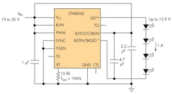
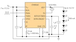
This issue has been addressed by making a switching power supply have a constant-current output (rather than a constant-voltage output), and making this current adjustable to implement dimming. The concept is shown in Figure 2 using the LTM8042.
2. A power supply designed for externally adjustable constant-current output, here done with the LTM8042, meets the drive needs of LEDs.
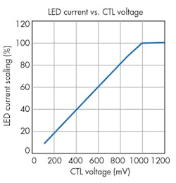
By varying the voltage on the CTL pin from 100 mV to 1 V, the LED current can be scaled over a 10:1 range (Fig. 3).
3. When the CTL pin on the LTM8042 is varied between 100 mV and 1 V, the LED current is then scaled over a 10:1 range.
This limitation in dimming ratio comes primarily from the difficulty in scaling the current-sense signal in the pulse-width-modulation (PWM) section of the switching regulator to very low levels. The dimming ratio can be extended by using the PWM signal to the LED to pulse it on and off. If this pulsing can be done at a high-enough rate—typically a few hundred hertz—the pulsing is not visible to the human eye. With this technique, the dimming ratio can be extended to 3000:1 (Fig. 4).
In this case, the LEDs are turned on and off by the clock signal applied to the PWM pin. While the pulsing isn’t visible to the human eye, it can be an issue for other applications, such as when the scan rate of a digital video recorder potentially interacts with the LED flashing to produce undesirable artifacts.
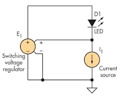
The technique here allows a wide dimming ratio to be controlled by a strictly analog means. It uses a hybrid approach in which a switching regulator holds the voltage across an adjustable current source constant, and puts the LED voltage inside a feedback loop so that variations in the LED voltage don’t affect the LED current. The voltage across the current source doesn’t have to support the LED voltage drop and its variations, and thus can be optimized for the best choice of power dissipation versus dimming ratio.
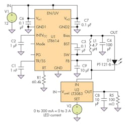
The conceptual diagram of the hybrid approach (Fig. 5) leads to the implementation using the LT8614 as the voltage supply and the LT3083 as the current source (Fig. 6).
5. The hybrid approach combines a switching regulator with an adjustable current source to extend dimming range.
With the input voltage of 12 V, the LED current is varied over a 0-to-3-A range via a 0-to-300-mV signal applied to the SET terminal of the LT3083. The IC’s OUT terminal follows the SET terminal, so a constant current flows in R5 via the relation:
I_R5 = V_SET/R5
The current in the IN terminal of the LT3083 follows the current in the OUT terminal very precisely until it reaches a minimum load value of about 500 μA. The LT3083 needs 510-mV worst-case dropout voltage from IN to OUT, as well as 300 mV for R5 at maximum current. The LT8614 holds the voltage at the IN terminal of the LT3083 at exactly 0.97 V, which keeps the power dissipation of the LT3083 at tolerable levels, peaking at about 2.4 W at 3 A out.
The LED cathode is held at 0.97 V by the LT8614, but the anode voltage goes to whatever voltage is required due to the feedback action of the LT8614. Additional LEDs can be put in series with D1 and the current will not change until the dropout voltage of the LT8614 is reached.
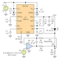
The LT3083 is a convenient part for the current-source function, but (as noted previously) it does have a minimum-load requirement. In addition, there’s a slight offset between the SET and OUT terminals, which is typically a few hundred microvolts but can be as high as ±6 mV over the temperature range. This offset places a lower limit on the dimming ratio. If a wider dimming ratio is needed, a discrete current sink using an op amp with low offset voltage can be used, such as with the LT6015 precision op amp as the control element (Fig. 7).
7. By adding a precision, low-offset op amp as a current sink, an even-wider dimming ratio is possible.
The LT6015 has a maximum voltage offset of ±250 μV over temperature, and the current source only needs about 100 mV dropout voltage. This allows the full-scale voltage to be raised to 600 mV, and permits dimming ratios in the range of 1000:1.
