This article is in Bob Pease on Analog Volume 2 in the Analog section of the Electronic Design Library.
Members can download the PDF ebook.
One day, back about 1966, I was going up the elevator at 285 Columbus Avenue in Boston to look at some production problems on Philbrick’s fifth floor. And who was in the elevator, but George Philbrick’s friend Jim Pastoriza.
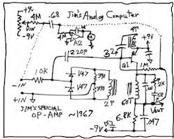
Jim was going up to show George his new analog computer demonstrator—portable and battery-powered. In fact, it was running, and he gave me a demo right on the elevator as we ascended. And, this modular analog computer ran on a couple of Jim’s new one-transistor op amps.
This is not an April Fool’s joke. This is not a hoax (see the figure). I don’t think anything ever came of that amplifier, though. Nobody else ever heard of it. It was never published. It was obviously the result of some kind of a bar bet. George must have bet a big bar bill on whether such an amplifier could be built. And Jim was gonna win the bet!
History Almost Repeats Itself
I did see the schematic of that amplifier, and it was very much like the one shown here. But I never did see the internals of the amplifier’s construction. Since I just remembered this amplifier after more than 40 years, I decided to re-create it. I got a group of likely looking transformers and tried to get them to ring when tickled. They would not ring with any decent Q when tuned with 1000 pF.
Finally, a friend had pity on me and loaned me a good, small (1.1-in.) Carbonyl C toroid. (Carbonyl is pure iron in powder form, embedded in a neutral matrix.) When wound with 60 turns, it had good Q. I put on a few more turns and lashed it into the circuit shown. It oscillated nicely at 0.7 MHz, using a 2N3906. (Jim had used a 2N384-type, which is a little hard to find these days.)
Then I added in the galvanically isolated “front end” with the V47 varactors, with the 220-pF feedback to the base of the PNP. I was able to wiggle the dc voltage at the negative input and modulate the amplitude of oscillation—and to move the dc output voltage a little. I fooled around with various variable capacitors, and trimpots, too, and twisted-pair capacitors. I got the “gain” up to 0.2 and then 0.4.
I borrowed our best “twiddle box” and it helped, as the capacitor had a knob on it. The 1.9k in series with 68 pF was rather touchy, but I got the gain up to 12. Then I added a little PFB with the 24k/5k divider. (I could get high gain in a small region, but it was not very linear, and even then, it had good high gain mostly when VOS was as gross as 0.5 V.) Finally, I got the gain error down to ±0.1 V for a ±1-V output swing.
Jim had said his gain was up at 1000. I was hoping I could get the gain up to 100, but none of my tricks could get it up there. Jim was a good engineer, and he knew a lot about varactor amplifiers, but maybe he never really got it to 1000. But it works okay even with a gain of 20.
The Results
Anyhow, I set up the big one-transistor kluge along with another low-power FET op amp as “A2” and ran them as an analog computer as Jim had showed me on the elevator. If you look at the output of A2, it starts out pegged. If you turn the VIN pot, you can bring the meter to a balanced state, but it’s moving fast. Can you manipulate that pot to get and keep the meter on-scale? After you understand that this is simply a double integrator, and after you practice a bit, it’s not very hard.
So, here is a little analog computer that you can use to practice closing the loop around a double integrator. And now you see that a one-transistor amplifier is not a hoax! Improbable, yes, but usable in a pinch. I haven’t given up on getting good gain, but I’ll spend no more time on it for now.
One of my friends reminded me that there’s one thing worse than a circuit with too many transistors, and that’s a circuit with too few transistors. Yeah, that’s true. But back in 1966, using a small number of those expensive transistors wasn’t a terrible idea. If I could only get the gain a little higher!
Comments invited! [email protected] —or:
Mail Stop D2597A
National Semiconductor
P.O. Box 58090
Santa Clara, CA
95052-8090


