Download this article in PDF format.
In Part 1 of the story behind the invention of the handheld calculator, we left off with the development of the power supply. Part 2 concludes the story, kicking off with how the keyboard came about…
The Keyboard
Thomas M. Okon, COMPLEAT Implementations Team Lead at Concur
In 1966, there were no cheap, reliable keyboards. The keyboards that did exist were too bulky and expensive to work for the calculator. Jim Van Tassel took on the task of designing a small, power-efficient keyboard. Van Tassel and Jerry Merryman together came up with the solution for the keyboard contacts.
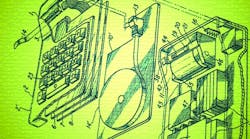
Underneath the keys are helix springs and thin, gold-plated, copper strips. Pressing a key shorts its strips with conductors on a printed circuit board referred to as the keyboard encoder. Those conductors connect to output terminals that get shorted in unique combinations to represent in a binary form which key was pressed. The unique electrical signal produced would then get transmitted to the processing circuitry. Van Tassel and Jack Kilby filed U.S. Patent 3,819,921 specifically for the keyboard keys and encoder.
Thermal Printing
For the display mechanism to show the request arithmetic and calculated result, the original idea was to use neon lights. They determined that wouldn’t work because neon lights required too much power. Another option was to use light-emitting diodes (LEDs). LEDs were being manufactured at the time by TI’s SC Division; however, they were expensive and difficult to produce. By their calculations, the LEDs would drain too much power from the calculator’s batteries. Kilby suggested they do thermal printing on paper tape.
In 1965, researchers in Kilby’s lab had developed the first semiconductor thermal printhead using monolithic, silicon integrated-circuit technology. The low-power printhead would “burn” images onto heat-sensitive paper. In 1966, the team decided to use the breakthrough technology to develop a built-in thermal tape printer for their calculator.
4. The Cal-Tech printer’s ceramic header consisted of 19 gold plated leads. Connections to the back of the IC were made through three holes using gold-wire thermo-compression bonding.
The thermal printer they created consisted of a silicon IC cemented to the back surface of a ceramic header. It used power from a 12-V system to heat up to 270°C. It had a heat time of 10 ms and was able to print about 12 characters per second.
Each of the three holes in Figure 4 had five thermally distinct leads. There were also leads for ground, +12 V, +3 V, and gate rail voltage. Small epoxy dabs were placed over the wire bonds to secure the gold wires. The back surface of the IC was a thermal printhead coated with silicon nitride for durability.
The print face consisted of a silicon 3 × 5 matrix of dots known as “hot spots,” which made contact with the thermal paper tape. The 3 × 5 dots were etched to be separate entities, so that they could be thermally distinct. Each of the 15 dots was directly heated by a drive transistor and its load resistor, which received current from a gold wire. Heating the dots in various combinations is what formed the display of numbers and characters.
When they first tried to use thermal printing, they found that it was difficult to direct current via the leads to just the hot spots, which were resistors. Jerry’s key innovation was to put switching drive transistors in the hot spots and place booster amplifiers on the same silicon chip. Jerry also put in an automatic circuit to sum the heat build-up and reduce the rate of the final pulses. That enabled the printing to be more legible. Without that circuit, the pulses tended to get too hot.
To prevent thermal buildup in the printhead, print duration was adjusted downward as a print cycle proceeded. Jerry wound up receiving three improvement patents on thermal printing. Those patents were later used in a number of TI products, including the first portable thermal printer, the Silent 700 Series Terminal, which was marketed in 1971.
To advance the paper tape of the thermal printer, the team tried to make a paper fork with a ratchet mechanism and a capstan. They didn’t wind up using it, though, because it required too much power. They needed something that could be powered by smaller battery cells. John McCrady wound up creating an inertia clutch in which a solenoid pulled a clapper comprised of a ferromagnetic material. By inertia, the clapper lifted the clutch out. The clutch and the clutch plate gripped the paper tape.
The paper drive was unique by virtue of the fact that driving the paper forward didn't occur when the solenoid was activated. Maximum force was applied when the return spring was fully compressed and electrical current was released in the solenoid. An internal clutch spring, which was secured to the clapper, would thrust the clapper forward. That advanced the paper tape forward a single character length.
McCrady wound up getting a patent (U.S. Patent No. 3,520,459) on the tape advance system used in the original calculator. When the calculator was copied in Japan by Canon Inc., they were able to make the ratchet and capstan work.
Excess-3 Binary Logic
To perform arithmetic operations on the numbers keyed into the calculator, each individual number was converted into a 4-digit binary (1s and 0s) form known as excess-3 (XS-3). XS-3 is derived by adding 3 to each decimal number and then converting the result to binary.
For example, the number 6 is encoded in XS-3 as the binary form of the number 9, which is 1001. For a two-digit number such as 56, the 5 and the 6 would get encoded individually. In XS-3, 5 is 1000 and 6 is 1001, so 56 in XS-3 is 10001001. Jerry chose to use XS-3 at the start of the project. He had read about it years prior and decided to use it based on the advantages over normal binary.
LSI Slicing
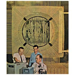
5. The photograph shows one of the four silicon circular slices (wafers), which contained the calculator logic. Each slice was mounted into an indentation on a square circuit board. (Courtesy of Gaynel Lockhart)
Three of the slice’s quadrants (top, left, and bottom) seen in Figure 5 have 42 overhanging, gold-plated, copper leads, which were etched and bonded to pads by ultrasonic agitation with a chisel. In the right quadrant is a large ground terminal.4 Each slice has a diameter of 1¼ in. and holes through the insulator, which is AZ photoresist. During the fabrication process, the team stacked the slices so that the composite yield could use one mask for the overlay to hook gates together. Out of the 52 slices they worked on, they got 24 of them to work.
Diffused into the square portion of each slice are 384 NAND gates (circuit cells). Each NAND gate is identically constructed with a size of 32.5 × 50 mils3, and consists of eight transistors, two resistors, six input terminals, one ground terminal, and one collector voltage terminal.6 The gates somewhat resembled a TTL, except they were very low power, lower voltage, and much lower current. The NAND gate was slower than TTL, but it didn't need to run fast.
Jerry's technician, David Atkins, hand-probed approximately 20,000 gates, and looked at the results on an oscilloscope to determine the location of the good cells. He denoted each gate with a check or an X, so that they could decide to use it or not. As far as they know, he didn't make a mistake. A channel-routing computer program was used to provide discretionary wiring masks for the 150 good NAND gates. When the 150 gates were first put together, none of the arrays worked. The team used a dental drill under a microscope to penetrate the epoxy encapsulation to repair them.
In October of 1966, Electronic Engineer magazine featured James Van Tassel, Jerry Merryman, and Gaynel Lockhart on the front cover with one of the calculator’s four slices in the background. The corresponding article describes the large-scale-integration (LSI) fabrication process.5
The First Working Prototype
By December of 1966, Jerry held a working prototype of the calculator in his hands. It was battery-powered with no wires attached. The prototype had the capability to add, subtract, multiply, divide, and print the answer onto paper tape. Multiplication was achieved by repeated addition and division by repeated subtraction.4 The device could accept six-digit decimal operands and print up to twelve-digit decimal answers. They still had to clean it up, though, and get everything mounted just right.
On Feb. 13, 1967, they completed the first electronic board, which had four arrays on it. While testing the prototype, they noticed it failed to place the decimal point correctly on certain problems. They had assembled a second set of electronics that did not have that error. In early March, they interchanged that second set with the original to create their first complete prototype.3 On March 29, 1967, 18 months after the project began, Jerry handed that prototype to Pat Haggerty.
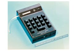
6. The finished calculator presented to Pat Haggerty in 1967 now lives at the Smithsonian in Washington, D.C. (Courtesy of Texas Instruments Inc.)
The prototype had 18 keys, including 0-9, +, ̶, ×, ÷, ., C (clear), E (error), and P (print). An on-off switch was located near the top to the right of the TI logo. The outside case was grey and made of a solid brick of aluminum they had hollowed out using a milling machine. It had dimensions of 4 1/4 inches width by 6 1/8 inches tall by 1 3/4 inches thick. The overall weight was only about 45 ounces.
The calculator available before theirs, the Sharp Compet CS-10A, weighed 55 pounds and cost $1,490. Their Cal-Tech calculator could operate for four hours until needing to be recharged. During those four hours, it could print 40,000 characters on 210 feet of thermal tape.
The team had spare parts left over, so they assembled two more prototypes. However, some of the parts were defective, so those other prototypes didn’t fully work. The prototype at the Smithsonian is the only one that really calculates properly. The second prototype was retained by Kilby, while the third was retained by TI’s Patent Department.
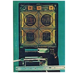
7. Inside the Cal-Tech calculator: The primary electronics for performing arithmetic calculations and generating control signals were on one plane within an “integrated semiconductor circuit array.” (Courtesy of Texas Instruments Inc.)
There were three separate, yet identical, 24-bit shift registers (Fig. 7, top). They were electrically connected by printed circuitry on a common insulating substrate to two resistors and the four integrated circuits used for logic. One register (Fig. 7, top left) was used for the keyboard operand, while the other two in series formed the accumulator.
Each shift register could hold six-digit decimal numbers, which was the nominal capacity of the calculator. When you keyed in a number, the number would go into the operand register. If you then hit the plus key, the number would be added to the accumulator. Work on the shift register resulted in U.S. Patent No. 3,573,754.
Jerry originally worked out a processing unit that only needed 400 gates. However, there were issues with getting the decimal point in the right place. Ultimately, he settled on a four-chip design with a total of 535 logic gates. The top left circuit (Array A) in Fig. 7 has 151 functional unit NAND gates. Array A has the adder and delivers the control signals to the thermal printer. The bottom left circuit (Array B) has 132 functional unit NAND gates. The top right circuit (Array C) has 135 functional unit NAND gates, and the bottom right circuit (Array D) has 116 functional unit NAND gates.6
The Calculator Patent
Texas Instruments originally filed a patent for the calculator on September 29, 1967. For the patent and disclosure, Jerry asked Gaynel to talk to the patent attorney and tell him how the whole calculator was pieced together. There was some back and forth with the patent attorney regarding other patents. Ultimately, two of the patent applications were abandoned due to revisions that had to be made. The final patent (U.S. Patent No. 3,819,921), titled “Miniature electronic calculator,” issued on June 25, 1974.
The Pocketronic
When the Cal-Tech calculator was completed, TI felt they still lacked the experience to sell consumer products.4 In 1969, they decided to form a joint venture with Canon Inc. in Japan to market the calculator. One of the Cal-Tech prototypes was sent to Canon for their engineers to examine.
In April 1971, Canon and TI introduced the first calculator on the market known as the Pocketronic. The Pocketronic was a copy in concept of the Cal-Tech calculator, except it used MOS circuitry (manufactured by Texas Instruments) instead of bipolar circuitry. The display mechanism was still under development, so the Canon calculator also used thermal printing.
By 1972, five million pocket calculators had been sold in the United States. In April of 1972, TI announced its own calculator, the TI-2500 Datamath, with an 8-digit LED display. They sold the calculator for a price of $149.99. By January 1976, it’s estimated that more than 100 million handheld calculators were in use worldwide.
In July 1974, a month after the patent issued, Jack Kilby wrote a letter to Harold “Hal” Levine, an Assistant Vice President and patent attorney at TI, indicating Jerry should get due credit for his contributions to the calculator. Kilby had high praise for Jerry's contributions and gave him credit as general manager for the project’s success, as well as for designing all of the electronic circuitry.
TI went on to fabricate and market very large integrated circuits under the name Discretionary Routed Array (DRA). It was an outgrowth of the technology used for the circuitry in Cal-Tech. Over a period of several years, TI sold DRAs to many customers, including IBM, Burroughs, and Raytheon. In December 1975, Jerry was elected as a TI Fellow for his work on the calculator, as well as for his pioneering work in computer-driven, opto-mechanical apparatus used in DRA and photolithography.
Having long been a student of optical design, Jerry was later assigned to the Computer Imaging Branch, where he applied optics and electronics to a family of high-speed laser writers used in submicron lithography. One of these was a 16,000-pound granite block machine with air-bearing stages writing 400 Mpixels/s with ½-micron pixels and ¼-micron addressability on plates up to 24 × 27 inches. According to the best available measuring machines, it had a root-mean-square accuracy of 0.15 microns.
In 1987, Jerry received the Haggerty Award for Innovation from Texas Instruments for his improvements to the design and development of thermal printing. Pat Haggerty presented the award to seven people for their work on thermal printing. Most of those people, except for Jerry, had worked at TI in Houston on the Silent 700 Series Terminals. In 1989, Jerry was awarded the Holley medal by the American Society of Mechanical Engineers. Other notable recipients include Henry Ford (1936), Edwin Land (1948), William Shockley (1963), Harold Edgerton (1973), and Soichiro Honda (1980).
In 1993, Jerry retired from TI after 30 years of employment. He later returned to TI as a consultant and worked on the digital-light-processing (DLP) chip program for mirrored television. DLP is considered one of the most technically challenging products ever produced by TI.1 In 1997, Jerry received the George R. Stibitz Computer Pioneer Award from Montana State University for co-inventing the first handheld digital calculator.
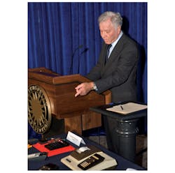
Jerry Merryman takes to the podium at the donation ceremony in 2007. (Courtesy of the Smithonian’s National Museum of American History)
On Sept. 25, 2007, in celebration of the 40th anniversary of the first calculator, TI donated some of the early calculators manufactured by TI (including the TI-30, TI-58, and TI-59) to the Smithsonian's National Museum of American History in Washington, D.C. At the ceremony, Jerry gave a speech before the audience of curators, teachers, and press.7 They brought the original calculator out and Jerry got to hold it again. He was surprised to find it still had the original batteries in it.
References
1. Edwin G. Millis, “Jerry Merryman: the man who killed the slide rule” (PDF), International Slide Rule Museum.
2. Jerry D. Merryman, "Making light of the noise problem", Electronics magazine, Vol. 38, No. 15, pp. 52-56; July 1965.
3. United States International Trade Commission, "In the matter of certain portable electronic calculators," Investigation No. 337-TA-198, Washington, D.C.; July 1985.
4. Kathy B. Hamrick, “The History of the Hand-Held Electronic Calculator,” American Mathematical Monthly, 102, October 1996, pp. 633–639.
5. Steve Scrupski, "Large scale integration in practice," The Electronic Engineer, Vol. 25, No. 10, pp. 118; Oct. 1966.
6. Jack Kilby, Jerry Merryman, and James Van and Tassel, "Miniature electronic calculator," U.S. Patent No. 3,819,921; Issued June 25, 1974.
7. Megan Gambino, "Calculating History: Remember the TI calculator models," Smithsonian Magazine; Sept. 2007.
