Capacitive Sensing: A Paradigm Shift for Encoders
Download this article in PDF format.
Encoders are a vital component in many applications that require motion control and feedback information. Whether a system’s requirement is speed, direction, or distance, an encoder produces control information about the system’s motion.
As the direction of electronics strives toward higher resolution, ruggedness, and lower costs, the encoder sensing mechanism is also improving in these areas. Traditionally, the encoder’s sensing mechanism has been optical or magnetic. But there’s a new player in town: the capacitive electric encoder. We’re going to talk about this new player and how it measures up to the encoding environment’s accuracy and ruggedness requirements.
Sponsored Resources:
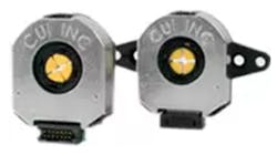
1. Different encoder types developed by CUI. (Courtesy of Digi-Key)
Encoder Classes
An encoder is a device that converts information from one format to another. In this article, the encoder is a motion detector with an electrical drive element. There are two different classes of electrical encoders: linear and rotary.
A linear class measures motion along a straight path, providing position, speed, and direction. This encoder has a sensor, transducer, and a location reader. An analog or digital output signal relays the encoder’s position to the system’s receiver. The encoder reads the information and identifies the encoder’s position. The encoder can provide speed or velocity data over time and with two sensors, the determination of direction is possible.
A rotary class, also called a shaft encoder, is a must-have in a hobby shop for driving motors. This device activates motors and measures rotational motion or angular position. The rotary encoder also has a sensor, transducer, and location reader. The reader relates the current position of the shaft to provide angular data to the user. The encoder also can provide speed or velocity data over time and with two sensors, it’s possible to determine the encoder’s direction.
Two Different Encoder Categories
The encoder output governs the category of the encoder’s category: incremental or absolute. An incremental encoder provides speed and distance feedback of any linear and rotary system. This category of the encoder device generates a plus train or a square wave to determine position and speed. Typically, the output signal is either zero or the supply voltage.
An absolute encoder generates unique bit configurations to track positions directly. The number of bits describes the resolution of these encoders. For a magnetic encoder, the number of magnetic poles determine that resolution. For higher-resolution optical encoders, there are more open segments for the light to shine through.
The physical implementation uses the three fundamental sensing fields to capture the element of motion. These three fields are optical, magnetic, and electric. The optical encoder incorporates a light-emitting diode (LED) and photodetector pair. The magnetic encoder uses magnets to create electromagnetic fields. The capacitive electric encoder employs capacitors and electrical signals. All three of these sensing fields provide the absolute and incremental information for the linear and rotary encoder classes.
Optical Sensing Encoder
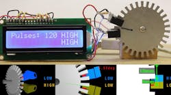
The most popular encoder field is the optical encoder, which can provide high-resolution results. This device has an LED light source, a notched rotating disk, and a photodetector. For a rotary encoder, the shaft rotates the disk to allow emitted light through disk notches to impinge on a photodetector. As the rotor spins, the resulting pulsed signal lands on the photodetector.
2. An optical encoder operates by sensing the through windows as the shaft rotates. (Courtesy of Digi-Key)
The optical encoders can successfully deliver high-resolution results, with an increase in the optical disk notches. The main components of the optical encoder are the optical disk, LED light source, photodetector, transimpedance amplifier, and analog-to-digital converter (ADC). Of these elements, the LED light source requires a high constant current during operation and a higher physical profile.
It’s useful to note that an optical encoder’s construction is fragile and highly sensitive to dust, dirt, and other environmental contaminants. Vibrations and temperature excursions can also be damaging or alter performance.
The optical encoder’s immunity to electromagnetic interference (EMI) depends heavily on the internal circuit layout and shielding. The current consumption typically is equal to or higher than 20 mA. This is especially critical in battery-powered applications. Finally, the LEDs have a limited half-life of approximately 10k to 20k hours, or roughly one to two years. As compared to the magnetic encoders, optical encoders are capable of higher-resolution and thus higher accuracy.
Magnetic Sensing Encoder
The core of a magnetic rotary encoder is a large magnetized wheel. This device generates output data by detecting changes in magnetic flux fields. With the rotary encoder, the motor turns the shaft and rotating disk. The disk contains alternating, evenly spaced, north and south magnetics; magnets are located on the outer, circular edge. This disk arrangement provides a rugged and robust solution.
The wheel spins over a plate of Hall-effect or magnetoresistive sensors. These sensors detect shifts in the positions of the north>>south, south>>north magnets. As the disk spins over the mask, there’s a predictable response in the sensor. A signal-conditioning circuit receives the magnetic responses and translates the signal into speed or position. The number of magnetized wheel pole-pairs and sensors, along with the type of electrical circuit, work together to determine the resolution of the encoder.
The magnetic encoder provides a very rugged solution, bringing high immunity to electrical and magnetic interference. The encoder also has a mechanically durable housing with no sensitive internal components, such as an LED. As compared to the optical encoders, magnetic encoders avoid the seal, vibration or impact, bearing failures, and LED degradation. Oil, dirt, and water don’t affect the encoder’s magnetic fields; however, the magnetic encoders aren’t as accurate as their optical counterparts.
Capacitive Electric Encoder
The capacitive electric encoder has three main parts: rotor, stationary transmitter, and stationary receiver. The capacitor rotor replaces a typical optical disk or magnetic disk with a printed circuit board (PCB) that has an etched sinusoidal pattern.
The rotor rotates, which causes the etched pattern to modulate in a predictable way. The measured capacitance-reactance in this system is between the two stationary boards as the rotor rotates. In the three-plate topology, the rotor is between the stationary transmitter and receiver boards.
3. Shown is the basic operating principle of a capacitve encoder. (Courtesy of Digi-Key)
A measurement is taken of the changing capacitance-reactance between the stationary boards as the rotor rotates. The capacitive encoder detects the change in capacitance-reactance by sending a high-frequency reference signal from the transmitter board and observing the field changes with the receiver board.
The raw signals of the capacitances in this system create a time-varying voltage. Two synchronous-demodulators followed by low-pass filters process this amplitude-modulated carrier to provide dc sine and cosine outputs. The cutoff frequency is highly flexible and limited by the internally generated noise. This noise is proportional to the square root of the cutoff frequency and sets a limit to the resolution. The standard capacitor encoder’s cutoff frequency is 1 kHz.
The total field integrates and converts the encoder’s output into a current, where the on-board electronics process that signal. This total process provides several dc output signals that are proportional to the sine and cosine rotation angle. This receiver essentially captures the modulated signals and translate them into increments of rotary motion.
The capacitive sensing encoder provides a combination of performance features that optical and magnetic technologies cannot match. This encoder provides fine and coarse channels that generate position and speed information, which is available through digital programming techniques. The combination of these two functions along with high-resolution ADCs and repeatable capacitances create a highly accurate environment. This is all accomplished with a low-power system that’s immune to magnetic and electric interference. The low-power consumption of the capacitive encoder outranks both the optical and magnetic solution.
The shielding of the rotary and stationary plates prevents the entry of external signals and contaminants into the mechanically durable encoder housing. This arrangement produces a low-profile, extremely rugged encoder solution. The shaft of the capacitive rotor is flat and hollow. Consequently, there are no bearings to cause wear and tear failures.
Capacitive electric encoders offer performance, reliability, and accuracy not available with traditional encoders. Important differences between optical and capacitive encoders is the optical disk and power dissipation of the latter. The capacitive electric encoder generally consumes 10 mA. It’s more robust, less susceptible to contamination, and consequently achieves a much longer life than optical encoders.
Another benefit of capacitive electric encoders is the ability to change the encoder’s resolution by modifying the line count in the electronics, without changing components. Compared to optical and magnetic encoders, capacitive versions simply provide the combination of high-resolution, ruggedness, and programmable flexibility.
Conclusion
The encoder is an electromechanical device that converts sensed mechanical motion to a digital signal. The encoder’s output digital signal provides position, velocity, and direction information. Today, encoder applications appear across the board in areas such as automotive, consumer electronics, office equipment, industrial, and medical industries.
The two dominant encoder types in the general industrial market are optical and magnetic. But the relatively new capacitive electric encoder surpasses both of those in terms of high resolution, ruggedness, and programmability.
Sponsored Resources:
Related References
The Advantages of Capacitive vs. Optical Encoders PDF
Innovative Rotary Encoders Deliver Durability and Precision without Tradeoffs PDF
Energy-Conscious Sensing for Mobile Motor Drives PDF
Other References
A Designer’s Guide to Encoders
Innovative Rotary Encoders Deliver Durability and Precision without Tradeoffs


