The Front End: Beware the One-Leaded Voltmeter (or, The Chronicles of GND)
At the time of writing, some colleagues are working on a demonstration for the big “Embedded World” show in Germany. They’ve plumbed in some natty speech-recognition technology into our super new dual-core PSoC. The buzz-phrase for this is “wake phrase recognition,” and all you up-to-date people out there have no doubt already used it when you intone “OK, Google” or “Hey, Siri” or “Dang, Alexa, I did not order paper towels.” The difference is that for personal-scale embedded devices like watches, rings, and earbuds without a permanent connection to “The Cloud,” the processing must be done locally and at super-low mean power.
I only mention it because this “wake phrase recognition” will be essential for the Engineer’s Smart Watch that I feel I must crowdfund rather urgently. It’s a special Smart Watch to be worn by any engineer who gets involved in electronic circuit or system design. Its unique feature is that it will deliver a painful electric shock to the wearer upon detecting a preset wake phrase of my choice. And the very first phrase that will go on its list is:
“voltage at”
as in:
“I measured the voltage at the junction of R5 and C3.”
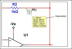
Accepting this phrase at face value is a symptom of a dread disease. I refer to this ailment as “Kirchhoff’s Madness,” and its main carrier is an imaginary beast that I call the One-Leaded Voltmeter. I say imaginary, because none of the meters I’ve ever seen for sale here in the real world have just one lead; two leads seem to be very much the order of the day.
The problem has become far more prevalent in this age of circuit simulation, where map is assumed identical to territory. Here’s one example I found in the wild after a quick search:
Now, I can live with this hypothetical one-terminal flourish when the currency of your simulation is a signal of unspecified (and irrelevant) physical form. Here’s a less harmful version, also found on the web:
In this type of diagram, the signals flowing along the connecting lines are just dimensionless carriers of information in a system-level simulation. No electrons are harmed or excited in the acquiring of that information.
What’s the Point?
What, then, is the problem that is getting me all hot under the collar? It’s this: Voltage is something that exists between two points, not at one point. You may recall from the physics of your youth that the potential between two points is the definite integral of the electric field along a path between those points (any path). The definite integral is required in order to eliminate the constant of integration. Trying to “measure” a “voltage” with a one-leaded meter is like trying to calculate a numeric value from an indefinite integral—you haven’t defined a path over which to do the calculations.
Of course, when pressed, the sufferer of Kirchhoff’s Madness will protest that the other lead of the voltmeter has been connected to (and here they often make a kind of reverential gesture) GND, by some higher authority. The existence of GND is axiomatic to their worldview, and all measurements of voltage require only the one true lead.
Now, there are circumstances where the temptation to take the two leads of a real voltmeter in two hands and go probing between points could be harmful. Experienced engineers can tell you that while low-voltage electronic systems can be designed with one hand behind your back, high-voltage systems are hazardous enough that you must work on them with one hand behind your back. In that case, you need to carefully attach “the other lead” of your voltmeter to one carefully selected reference point and leave it there while you go exploring with the other lead, monomanually.
Back to the watch and the punishment shock. The moral of today’s tale is this: Always make it clear where both leads of your voltmeter are connected, when you declare that you have measured a voltage. If there’s an unambiguous place where you feel comfortable in parking “the other lead,” write down what that place is, and attempt to show it on the circuit diagram of your design. This will, of course, rapidly illustrate that almost every modern electronic circuit diagram fails explicitly to define this one critical node.
A useful tip is to take a photograph of the setup in front of you, so that everyone can see where that other lead went. This can help the more experienced members of your team figure out that the reason your measurements or ‘scope traces suck is that this was a bad place to connect that lead. #NotKidding.
To and Flow
Another common symptom of Kirchhoff’s Madness is the belief that current flowing down a wire is akin to water flowing in a pipe, as delivered to you by the water company. You do what you want with this water, but it never gets back to the water company, instead just soaking into your lawn or draining to a sewer somewhere.
When (mis)applied to electronic circuits, this thinking commonly leads the incautious into trouble. The temptation is to believe that currents that flow to—look, there it is again—GND, somehow disappear, like the spider that a parent brushes off the bed with a casual “it’s gone now.” Nope. That current is still flowing, in a closed loop that will eventually get it right back to where you first encountered it—after it has had some interesting adventures, causing trouble in places you weren’t looking. A bit like that spider.
Lest you should feel that I’m lecturing you from the ivory tower vantage point of “well that never happens to me,” let me confess one manifestation (out of several) of Grrrr-ound that catches me out to this day. The only way to really appreciate a mistake is to make it yourself (like cake or a good cocktail, I suppose). This one’s due to the ground lead on the scope, which, under most circumstances, should be robustly attached to your choice of GND node on the board.
But what if that’s the only way that “GND” can actually get to your board, because of some power-supply wiring mess-up? If you never test the board without the scope ground (or BNC lead ground, same effect) then you’ll never see it not work. But the careless measurer with the one-leaded scope will detect the defect immediately…
There may well be more tales from “The Chronicles of GND” in future Front End pieces. For now, can you think of a time when the “voltage at” shock would have worked as a wake-up call to ensure you connected your voltage measuring device correctly? Let me know!


