Bob Pease had a special love for voltage-to-frequency converter circuitry. I did a vamp on his writing in an article of my own. If you want to measure a voltage in a remote location, it might be easier to send a series of pulses over a long wire, rather than send the voltage itself. The pulses are more resistant to noise, and you can clean the noise out of the pulse signal easier than try to reject noise out of a pure analog voltage. V-to-F circuits also have great dynamic range and will work over several decades of frequency.
Measuring a pulse-train frequency just requires a microcontroller or logic circuit using a cheap accurate crystal. That can be more cost-effective than measuring a voltage, where you need an accurate reference chip.
Still, your system might have an accurate reference anyway. When I designed automotive diagnostic equipment at HP, I noted that, “You need a rock and a ref.” This was a jaunty shorthand to say you needed a quartz crystal oscillator for accurate time, and a good reference to measure voltage. With those two, you can derive current, and power, and most of whatever else you want to measure. In a way, using a V-to-F converter means you’re pushing the reference requirement to the sensing chip. If you can develop an accurate V-to-F circuit, then you don’t need a separate reference chip.
Saying the V-to-F has great dynamic range is a way of saying the output is very linear. It’s accurate over a wide range of input voltages and output frequencies. That’s a great deal, compared to the headaches of ensuring a sampled data system remains accurate no matter the range of the input voltage. Once you add attenuation and range amplifiers to a system, things get pretty difficult and complicated.
I tried to use analog switches to make an attenuator in that HP diagnostic equipment I worked on. I had all kinds of problems with stray capacitance and accuracy issues, so I called Jim Williams at Linear Technology, now part of Analog Devices. He asked what I heard when I changed the vertical range on my Tektronix scope. I said that I heard relays clicking. Williams said they used relays since doing a solid-state attenuator is nearly impossible for high frequencies and voltages. Using a V-to-F converter might save you all of these headaches.
The LM331 and V-to-F
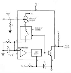
1. The block diagram of the LM331 represents a relaxation oscillator that will change frequency with input voltage. The output is a pulse train, not a square wave; hence the one-shot. (Courtesy of Texas Instruments)
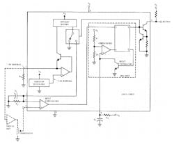
To understand V-to-F conversion, the LM331 datasheet is a great place to start. The applications section was written by Pease. Several application notes published by Texas Instruments were most likely also written by Pease. These notes are all linked to on the LM331 product page. The fundamental app note, “Versatile Monolithic V/Fs can Compute as Well as Convert With High Accuracy,” was released in 1980, at the same time as the part. The app note shows both a simple and detailed block diagram of the part (Figs. 1 and 2).
2. A more detailed block diagram of the LM331 reveals the R-S flip-flop, the internal bandgap voltage reference, and a current mirror. The bandgap output voltage is available on pin 2, which you also use to set the internal current mirror with a load resistor. (Courtesy of Texas Instruments)
You can also use the LM331 to make a frequency-to-voltage converter. The app note “Frequency-to-Voltage Converter Uses Sample-and-Hold to Improve Response and Ripple” shows how to remove the output ripple from the circuit while still keeping a speedy response time. You can think of it as a form of synchronous demodulation. It samples the output voltage at the same point in the ripple waveform. This note builds on the basic F-to-V app note, "V/F Converter ICs Handle Frequency-to-Voltage Needs."
Another vamp on the basic V-to-F converter is the current-to-frequency converter. There’s another nice app note for that, “Wide-Range Current-to-Frequency Converters.” The app note describes ways to build on the inherent wide dynamic range of the LM331 to make circuits that can work down to picoamperes of input current. While you have to add a lot of circuity to get that performance, it’s a testament to the versatility of the LM331.
3. The folks at Boldport make a nifty kit based on a Pease application circuit in the LM331 datasheet.
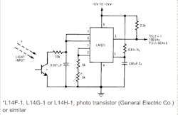
Going through the drawers of my home lab bench, I uncovered an LM331 voltage-to-frequency IC demo board given to me by the folks at Boldport (Fig. 3). Dr. Saar Drimer, the electronic artist behind Boldport, packages the board in a handy kit that you can order from his website. The kit has a Bob Pease quote “My favorite programming language is solder.” The kit is based on Figure 20 from the LM331 datasheet (Fig. 4).
4. This LM331 datasheet circuit is the basis for the Boldport kit. The kit substitutes a photocell for the photodiode, adds an output LED, and slows down the frequency so you can see the LED blink. (Courtesy of Texas Instruments)
Drimer added an output LED so that you can see the output frequency change. Another difference is that while Pease called out a phototransistor, Drimer’s kit uses a photo-conductive cell. Drimer also slowed down the frequency so that you can see the LED blink. Micah Scott has a video build of the kit:
The Art of the Science
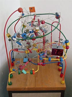
Most of us have heard about STEM (science, technology, engineering, and math). I first heard the term “STEAM” from my pals at Evil Mad Scientist. The added “A” stands for “art.” Boldport is an advocate of the artistic side of engineering, as evidenced by the whimsical traces on the LM331 Pease PCB (printed circuit board). While the artistic aspect of circuits seems to be blooming, it’s nice to know that analog geniuses like Jim Williams used to make working sculptures out of electronic circuits decades ago. Williams’ best friend, Len Sherman of Maxim Integrated, even made up a book of various Williams creations (Fig. 5).
5. Here’s one of Jim Williams’ working electronic art pieces from the book put together by his friend Len Sherman. It’s as if a Digi-Key truck hit an Alexander Calder sculpture. (Courtesy of Len Sherman)
We analog folks also know there’s art in the circuit theory and the mathematics that underlay the theory. It might be easier to buy a cheap microcontroller from Microchip, TI, or NXP than use an LM331. The thing is, the design and implementation of the LM331 is worth understanding just so you know the principles of analog design. While chips come and go, the principles of analog are timeless.
