Download this article in PDF format.
In many applications, there’s a need to determine the difference in arrival time of two pulses, such as those derived from acoustic signals emanating from a single moving source. In this circuit, logic signals indicate the timing of the acoustic signals with good fidelity. (An analog front end, not shown here, shapes the analog signals and converts them to digital-logic signals.)
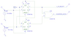
This circuit uses a dual-D flip-flop and an OR gate (Fig. 1) that provides a positive-polarity gate signal as well as an indication of which pulse came first, to be used by an MCU counter. Note that the OR gate could be eliminated if two MCU counters were used, one for each of the U1A Q and U1B Q outputs. In that case, only one of the two counters would accumulate counts, depending on which pulse arrived first and the time of arrival of the second pulse. Then, with additional coding, it would be possible to determine which pulse came first, and by how much.
1. By controlling timer count, this dual flip-flop circuit can determine which of two pulses arrived first.
This particular project required taking left, right, up, and down timing measurements, which would require four counters with gates—that’s two more than the PIC MCU designated for the project could provide. Therefore, using the OR gate saves MCU resources.
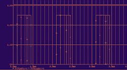
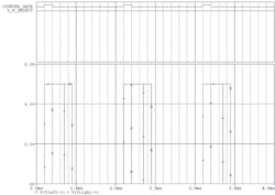
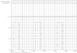
Vleft and Vright resting levels may be 1 or 0; but if 1, the timing between left and right pulses will be measured on the trailing edge of the pulses. This may induce errors if the pulse width of the trigger inputs is inconsistent. As the rising edge of Vleft clocks a logic 1 into U1A Q (L_R_Select), the U1B flip-flop is reset, thus forcing U1B Q to logic 0. A later pulse from the Vright source reverses this condition, ending the counter interval. Figure 2 shows the waveform timing for “right came first,” while Figure 3 shows the opposite case of “left came first.”
2. The Vright pulse arrives 100 µs before the Vleft pulse. Note that L_R_Select is low. If this signal is sampled by the MCU just after the gate signal goes high, this indicates right-before-left.
3. The Vleft pulse arrives 100 µs before the Vright pulse. Because the L_R_Select is high, if this signal is sampled by the MCU just after the gate signal goes high, this indicates left-before-right.
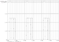
In the case of simultaneously arriving pulse edges (Fig. 4), there will be no gate output, which will result in zero counts accumulated by the PIC counter. The resolution around zero is limited by the rise and fall times of the flip-flop logic family used. Though the 4000-series logic family is fairly slow, it was adequate for this project. Faster logic families will allow for more resolution around zero, if that’s a requirement.
4. If both signals arrive with the “simultaneous” window, zero counts are accumulated by the PIC counter.
The clock frequency can also limit resolution; the maximum count at 500 kHz is 110. The overall span is double that as the sound source moves from left to right, relative to the center line of the two sensors and the display. Higher clock frequencies may require a 16-bit or greater counter, depending on the maximum difference in time of arrival; this project uses a 500-kHz clock for 2-µs resolution. The maximum time difference to be measured is defined by the time of flight of the acoustic pulse in air over the distance from one sensor to another. Three inches at a wave velocity of 1135 feet per second (fps) limits the difference in arrival times to 220 µs.
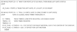
5. This code shows how the dual FFT timing signals can be used to indicate left or right motion, relative to the center of a display.
Some pseudocode (Fig. 5) illustrates the method for using the circuit output to indicate position or motion, where PortC.0 is the Counter_Gate signal and PortC.2 is the L_R_Select signal, also known as LR_FLAG.
Dave Conrad, a retired electronics engineer, creates innovative light-show systems using LED or video displays, and also does some contract consultation.
