Download this article in PDF format.
Back in 1999, Bob Pease touched on the operation of CMOS transistors in subthreshold mode. In his article, he pointed out that analog designers can use CMOS ICs such as the CD4007, a dual matched pair of transistors with another pair arranged as an inverter. Pease noted:
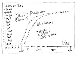
“Everybody knows that FETs are characterized by the threshold which causes the FET to put out ID = 1 µA. So currents below 1 µA are sort of imaginary, right? Wrong. Everybody knows that FETs have a square-law characteristic. As the current gets smaller and smaller, the gm [transconductance] per microampere keeps rising to very high levels. Wrong again. The gm per milliampere rises, but tapers up to levels such as 90 or 120 mV per decade. These transistors behave exponentially at low levels, just like bipolars.”
Pease had characterized the subthreshold performance of the CD4007 and included one of his famous hand-drawn figures (Fig. 1). What a digital designer might dismiss as leakage current is a predictable and useful operation mode of CMOS transistors. Pease knew this in 1999, but many analog engineers appreciated this fact. Robert Chao, of Advanced Linear Devices, worked at Supertex (now part of Microchip Technology). While there, he helped develop ICs used in smoke detectors. Long battery life is essential in a smoke detector.
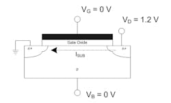
When Chao founded ALD, he used his knowledge of the low power dissipation of CMOS to design comparators and other low-power circuits. He, too, was fascinated by the subthreshold mode of CMOS transistors (Fig. 2). Chao points out the exponential relationship between gate voltage and drain-source current. Chao notes a change of 100 mV on the transistor gate causes a change of a decade in the drain-source current. This is pretty constant from 5 pA to 1 µA of drain-source current. With such wide swings of current for a small gate voltage change, you should either use precision MOSFETs that have narrow tolerance of gate threshold, or factory-select parts that do match threshold values.
Low Power, But Low Speed
Digital IC designers also appreciate the low-power properties of subthreshold. The 2006 book Sub-threshold Design for Ultra Low-Power Systems describes the techniques used for memory and logic design. In 2010, Scott Hanson founded Ambiq Micro out of work he did at the University of Michigan. Ambiq sells real-time clock (RTC) chips as well as complete microcontrollers using subthreshold design techniques. They claim a 13-fold power reduction over conventional chips.
Every analog engineer knows you can’t get something for nothing. The penalty with subthreshold design is the lower speed these circuits must operate at. All loads, even those internal to an IC, have a capacitive element. Since the effective resistance of a MOS transistor in subthreshold mode is in the hundreds of megohms, it takes a long time to charge up a load capacitor to its end voltage. In his Master’s thesis, “SUBTHRESHOLD CIRCUIT DESIGN AND OPTIMIZATION,” Sungil Kim points out that, “Unlike the traditional circuit design that uses a supply voltage greater than a threshold voltage, a subthreshold circuit design saves energy at the expense of performance." Kim goes on to note that there’s a quadratic exponential relationship with switching power versus supply voltage. He accomplished a 99% reduction in circuit power by operating the IC design at 0.55 V.
Many designers still like the old CD4000 series logic alluded to by Pease. Introduced in 1968, it can run on 18-V supplies. The absolute maximum power supply rating is 20 V, which gives it great noise immunity. It’s slow, but low power. The process is also rad-hard; it will work in high-radiation environments like space or nuclear power plants. When I was at the ESL division of TRW in the 1980s, we were using 4000-series logic in satellites. They are still available in those ceramic dual-inline packages.
While Pease was not hesitant to operate a CD4007 in subthreshold, remember it is a simple matched pair of P- and N-type CMOS transistors. You can’t run a digital gate like the CD4001 on less than the threshold voltage. Texas Instruments characterizes its CD4001 at 5, 10, and 15 V. But they will work at below 5 V, just without the certainty of 5-V operation. IC process technology is so good compared to the old days. I would be pretty confident about testing at a lower voltage and using it in non-critical applications.
The Impedance Factor
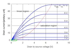
Subthreshold is an extension of that old CD4007 part that Pease mentioned. You can think of a MOS transistor in subthreshold range more like a variable resistor (Fig. 3). Like all analog things, it’s great the resistance is high when it comes to power consumption. High impedance is not so good when you have to charge up a load capacitance. It’s fine to have high impedance inside an IC; there’s no humidity or printed-circuit-board (PCB) leakages to cause you grief.
System designers have to be more careful with high-impedance designs. You may need to coat PCBs with Humiseal or a similar product. You may also have to pot the boards completely to ensure that no leakage interferes with the high-impedance circuit.
When I consulted to HP, I worked on a data-acquisition instrument for automotive diagnostics. The analog-to-digital converter (ADC) front-end had a spec of 10 MΩ. It’s a remarkable achievement that Keysight can get 10-GΩ input impedance on the venerable 34401A voltmeter. But for a PCB that slots into a personal computer in a hot, dusty, sweaty garage, 10 MΩ was too high. I got the customer to accept a 1-MΩ input impedance spec. That’s plenty high for anything you need to measure on a car, but low enough that we stopped having returns. Those returns always came from the South, or Italy, or other high-humidity locations.
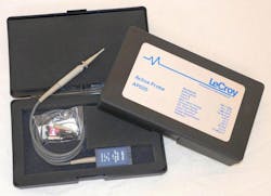
You should always keep speed and impedance in mind as an analog tradeoff. When you use your oscilloscope, its mostly with 1-MΩ input-impedance probes. To measure fast circuits, you kick the scope into 50-Ω input mode and bring the measurement in over a SMA or BNC coax cable connector. There are workarounds. Using a FET probe means you can get the high impedance, as well as the speed (Fig. 4). That’s why companies like Linear Systems still sell JFETs and FETs that give high impedance, fast speed, and low noise.
The RTC chip with minuscule power consumption made by Ambiq does not have to be very fast. Thing is, one day companies might combine subthreshold design with a low-capacitance process like Texas Instruments' VIP10. It’s a dielectrically isolated process. Every transistor is not only isolated by trenches, they are in a little glass boat formed by a silicon-oxide layer underneath the circuitry. If you can lower the capacitance that your subthreshold circuit has to drive by a factor of 10, you can speed it up by the same factor. All of this is good news for engineers who need absolute minimum low power in their designs.
Subthreshold circuits operate at very low voltages, so you should be able to operate off of less than 0.9 V, the voltage of a discharged alkaline battery cell. Whether you are an analog designer rolling your own subthreshold circuits, or a digital designer looking for ultra-low power, subthreshold might be for you.
