Download this article in PDF format.
When talking amplifiers, I sometimes get the impression that whole groups of electronics hobbyists and engineering students have been brainwashed by endlessly hearing and repeating the mantra “Gain-bandwidth product is a constant.” Hearing this statement so often, they actually start to believe this is a universal truth.
I was reminded of this once again some time ago, when I saw a video on the otherwise excellent YouTube channel “w2aew.” At around minute 2:23, the host says “...for a single-pole response, the product of the DC-gain and the bandwidth is constant":
However, this statement isn’t universally true—sometimes it’s true, sometimes it’s approximately true, and sometimes it’s completely wrong.
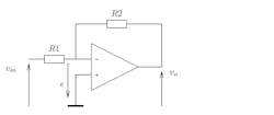
You might have thought I was going to tell you about the case of a voltage amplifier with a current feedback op amp—a statement that you probably already knew isn’t true—but I am not. Instead I’ll focus on what’s probably the simplest op-amp voltage amplifier configuration you can imagine, the mother of all op-amp circuits: the inverting single-pole op-amp amplifier shown in Figure 1.
1. Standard inverting op-amp amplifier.
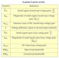
To avoid confusion, let’s first define all symbols that will be involved (see table).
To deduce the connection between AOL,0, BWOL, ACL,0, and BWCL, all we need to do is apply Kirchhoff’s law to the inverting node of the op amp. We assume our op amp is or can be approximated by a single-pole model, which means we can write:
Applying Kirchhoff’s law gives:
We also have:
which gives us:
Substituting Equation 1 in Equation 2 gives:
Equation 3 might look a bit daunting at first sight, but it was intentionally written that way to allow identification with a single-pole representation of the system:
Inspecting Equations 3 and 4, we get:
Multiplying the respective left and right sides in Equation 5 gives us the following exact formula:
Equation 6 is seldom used because in most practical cases:
which implies:
and therefore the equation can be rewritten as:
A closer look at Equation 7 shows the cause of the problem with the mantra: Only when ACL,0 is substantially greater than 1 can that equation be approximated by ACL,0 · BWCL = AOL,0 · BWOL for the standard inverting op-amp amplifier. If this isn’t the case, though, we can get a substantial error.
Take, for example, the case of a phase inverter (i.e., R1 = R2 or ACL,0 = 1) with a 741 op amp, for which AOL,0 = 200000 and BWOL = 5 Hz. Using the mantra, we would find a closed-loop bandwidth of 1 MHz. However, using Equation 7, we find the correct bandwidth to be 500 kHz, which means the mantra gives us an overestimation of the bandwidth with a factor 2! More generally, the procentual error on the predicted closed-loop bandwidth using the mantra-formula is given by:
So, if you want your prediction to be less than 5% off, your closed-loop DC gain should be at least 20, i.e. 26 dB.
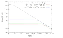
2. Amplitude characteristics for a standard inverting op-amp amplifier.
The graphs in Figure 2, which were made using PSpice and a first order op-amp model, also show ACL,0 • BWCL ≠ AOL,0 • BWOL, since the oblique asymptotes of the closed-loop system don’t coincide with the one of the open-loop system as is often erroneously drawn in textbooks.1 To clarify this point, consider:
For f → ∞, this becomes:
Considering the vertical axis in Figure 2 is in dB and the horizontal axis is logarithmic, we get: 20log(ACL) = 20log(ACL,0BWCL) − 20log f. The term 20log(ACL,0BWCL) determines the vertical position of the oblique asymptotes. Because of Equation 7, the latter term is equal to:
and obviously a function of ACL,0 itself. Only if ACL,0 >> 1, the oblique asymptote of 20logACL will coincide with the one of 20logAOL.
As an afterthought, note that for a standard non-inverting op-amp amplifier, the mantra-formula is correct, but for the standard inverting configuration you’d better memorize (1 + ACL,0)BWCL = AOL,0 BWOL from now on.
When actually measuring the bandwidth of the above-mentioned unity-gain inverter, don’t be surprised if you notice some peaking in the amplitude characteristic. This is caused by a complex pole in the real 741 and the presence of parasitic capacitance between the inverting and non-inverting input of the op amp, but that’s another story.
Hugo Coolens received his engineering degree in electronics in 1983 from KIHO Ghent. He is currently head lecturer at the Faculty of Engineering Technology, KU Leuven TC Ghent.
Reference:
1. Willy M. C. Sansen, Analog Design Essentials, p.155.


