Understanding System Protection: What You Don’t Know Might Hurt Your System
It’s Friday night and a frantic call from the operations vice president wakes the chief engineer in the middle of the night. “Our factory is down!” the VP cries out. Apparently, there was a heavy storm in Oklahoma City. There were lots of lightning strikes, and now the factory has stopped working. Now the chief engineer must cut short his mini-vacation with his family in Cabos San Lucas and take the next flight home to Oklahoma. The factory going down is a “life and death” matter that the chief engineer must address immediately.
Oklahoma is hit by 1,017,989 strikes per year on average, according to data from Vaisala's U.S. National Lightning Detection Network. This is second only to Florida, the number one state with the most lightning strikes—a whopping 25.3 strikes per square mile and 1.45 million lightning strikes each year, on average1.
What can you do to prevent this mishap from happening to you? How do you protect against faults that might damage your equipment, take down the factory, shorten your vacation, and perhaps jeopardize your career?
In the past, protection circuitries were bulky, expensive, and difficult to implement. Fortunately, advances in modern protection circuits have provided system engineers with robust, highly integrated, and easy-to-implement protection solutions.
Why System Protection?
All systems are subject to voltage, current, thermal, and other faults. Proper protection is critical for system uptime. Designers who don’t take these factors into consideration struggle to complete their system designs successfully during the design verification test stage. Or worse, they face line down situations on the factory floor. In the next sections, let’s discuss common system faults in three main categories: voltage, current, and thermal.
Voltage Fault
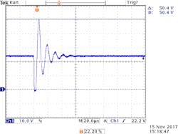
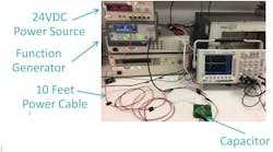
System Voltage Surge and Ringing: Lightning strikes, a blown fuse, a short circuit, a hot-swap event, cable ringing, etc. can all cause the input voltage to go higher and/or lower than the normal dc voltage range. Figure 1 demonstrates a short-circuit event where a brief short circuit at the end of a 10-foot cable can cause its voltage to ring and peak to 50.4 V, doubling its 24 Vdc normal voltage. Furthermore, the voltage also rings down to about 11 V (from the initial short circuit to 0 V). A robust system must either continue to operate throughout this ringing without interruption or at least survive it without damage.
1. Long cable voltage ringing after a brief short-circuit condition (top), test circuit setup (middle), and test circuit schematic (bottom).
Similar voltage ringing also occurs during a hot-swapping event where a card with a discharged capacitor is plugged into a live backplane (Fig. 2), or when a fuse is blown elsewhere in the system. The situation gets worse when the system dc voltage has a wide range. For example, IEC61131-2 defines an industrial programmable logic controller (PLC) with 24 Vdc nominal rail voltage with -15% to +20% tolerance and +5% pk ac component on top of it. So, the 24 Vdc rail can be at 19.2 Vdc minimum and 30 Vdc maximum. If we start with 30 Vdc power source in the above experiment, the peak ringing voltage would easily reach 60 V.
2. Hot-swapping a system card.
A lightning strike can cause a high-energy surge voltage. This typically can be handled by a front-end transient voltage suppressor (TVS) device and input filter. In a 24-V bus system, an industrial system typically uses a device like SMAJ33A to clamp it. Under surge conditions, this TVS device can clamp the surge voltage to 53.3 V maximum. So, any electronic component connected to this 24V bus must be able to withstand at least 53.3 V.
Input Reverse Voltage: Although rare, system miswiring can happen. For example, a car battery gets connected backwards. Another example is in a rack-mount system, where a person plugs in a card in reverse, or connects the power cable with the wrong polarity, etc. When the input voltage drops suddenly (input shorted or rings low), the output capacitor is now at a higher potential, causing a reverse voltage condition. A similar condition occurs when the output is suddenly shorted to a higher voltage rail (in a bundled cable, for example). Input reverse voltage faults rarely happen but can cause costly damage to the system and must, therefore, be prevented.
Current Fault
Overcurrent/Short-Circuit Fault: The obvious current faults are output overloading and short circuiting. Overcurrent loading is caused when the system runs over capacity. A faulty component on a board can form a short circuit. If someone accidentally drops a wrench onto the power connector or drills into a cable bundle, these actions can also cause a bad short circuit. If not protected, a board can suffer permanent damage or, worse, catch on fire.
Inrush Current: When a board with a discharged capacitor is plugged into a live backplane, a surge of current rushes in to charge up the capacitor. This inrush current, if not controlled, will follow this equation: I = Cdv/dt, where I is the inrush current, C is the capacitance, and dv/dt is the rate of change of the capacitor voltage over time. If a discharged capacitor (at 0 V) is plugged into a live backplane at 24 V, dV/dt in this case is instantaneous (infinite), translating to I = infinite. Without inrush control, this infinitely high current spike can damage connectors, blow up fuses, and cause voltage ringing on the backplane voltage.
Reverse Current: When a reverse voltage event occurs, as explained in the “Input Reverse Voltage” section above, current flow in the reverse direction can cause severe damage to the system.
Thermal
Over-Temperature Protection: When the temperature of a system or a component reaches a dangerous level, over-temperature protection shuts down the system to prevent damage and possible fire problems. Properly designed systems should operate without ever going into over-temperature shutdown. However, over-temperature shutdown does occur following a primary fault condition such as: an extended overload condition, a failed or failing system fan, accidental blocking of the system air inlet/outlet, or failure of the room A/C, etc.
Thermal Protection: What is the difference between over-temperature shutdown and thermal protection? Thermal protection has more intelligence. Instead of waiting for the temperature to reach critical threshold and shut down, thermal protection gives the system warning and choices when the temperature is rising higher than normal operation due to a primary fault. The system can choose to shred non-critical loads, running at a lower switching speed, etc. to dissipate less power. Thus, the system might be able to avoid an over-temperature shutdown with reduced system performance until the primary fault is resolved.
System Protection Solution
Design Challenge
System engineers who want to protect their products fully face some design challenges: a discrete or partly integrated IC implementation requires lots of external components; the tolerances stack up of the components is tedious to analyze and is hard to verify and guarantee performance over time; the resulting solution is large due to the high number of components.
Modern System Protection Features
Ideally, a system protection solution should be highly integrated, easy to design-in and easily pass design qualification. Here are some key features of a modern protection IC:
- Integrated PFET and NFET for forward/reverse voltage/current protection
- Integrated precision current sensing
- Programmable UV/OV, current limit thresholds, and fault response modes
- Thermal protection with warning flags
A Modern System Protection Solution Example
To protect my system against all of the circuit faults discussed, I’ve selected MAX17608/9. These are the industry’s most highly integrated, space-efficient, and robust ICs for high voltage protection at 1A load current. These products address both the increasingly stringent machine safety standards and the need for smaller solutions as modular rack PLCs continue to shrink and become denser with increased I/O capability.
Figure 3 shows the MAX17608/9 application circuit schematic. The IC operates from +4.5 V to +60 V and can withstand negative input voltage to -65 V. It includes integrated PFET and NFET for forward/reverse voltage/current protection, programmable UV/OV, current limit thresholds and fault response modes, and thermal protection with warning flags. All of this comes in a tiny 3- × 3-mm, 12-pin TDFN-EP package.
3. A highly integrated, space-efficient protection IC.
Aside from all the desirable integrated features, this IC has very precise current sensing at ±3%. A discrete solution can typically get you ±20%, so this is a significant performance improvement. I also need to monitor my system current consumption and am delighted to find that voltage on the SETI pin gives me just that, for free.
Summary
All systems are subject to voltage, current, thermal, and other faults. Proper protection is critical for maintaining system uptime. Designers who don’t take these factors into consideration struggle to complete their system designs successfully during the design verification test stage. Or worse, they could face line down situations on the factory floor. Fault happens, but you don’t have to be a victim—you have a choice to do something about it.
Reference
1 https://www.livescience.com/14714-lightning-prone-states-110620.html


