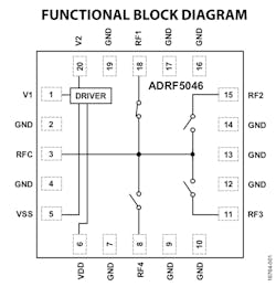
Whether due to or despite all of the attention that non-silicon processes are receiving for designs in the tens-of-gigahertz region, silicon-based ICs aren’t standing still. Rather, they’re addressing critical circuit-path blocks. An example is the just-released ADRF5046 from Analog Devices (ADI), an electronic, non-MEMS single-pole, four-throw (SP4T) device for signals from 100 MHz to 44 GHz that provides a simple yet vital function for the RF signal chain (Fig. 1). Representative applications include scanners; test instrumentation; mm-wave 5G cellular infrastructure; military radios, radars, and electronic counter measures; and very small aperture terminals (VSATs).
1. The simple functional diagram of Analog Devices’ ADRF5046 SP4T switch, which operates to 44 GHz, doesn’t show critical design-in issues such as parasitics and S-parameters.
The reflective switch design features insertion loss of 1.5, 2.5, and 3.0 dB at 18, 40 , and 44 dB, respectively, along with isolation of 46, 33, and 31 dB at those frequencies. Linearity is also a critical parameter; typical values for the ADRF5046 are 27.5 dBm (P0.1dB) and IP3 of 50 dBm. The switch handles RF power levels to 27 dBm for both through-path and hot-switching modes.
The five RF ports (common plus four switched) are dc-coupled to 0 V, so no dc blocking is required at the RF ports when the RF line potential is equal to 0 V. Furthermore, the RF ports are internally matched to 50 Ω, limiting the need for external matching networks.
The integrated drivers implement logic functions and offer a simple CMOS/LVTTL-compatible control interface where two digital-control inputs establish the RF path. The switch design is bidirectional with equal power-handling capabilities. At these frequencies, size matters, as smaller size minimizes parasitics and interconnect issues that will always be present. However, its 20-terminal, 3- × 3-mm LGA package should help here.
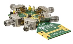
2. The 3- × 3-mm ADRF5046 is dwarfed by the requisite edge-launch, 2.4-mm RF connectors of its ADRF5046-EVALZ evaluation board.
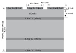
The device itself is only part of the design-in story, as the physical connection arrangement is a story of attention to details, S-parameters, and those unavoidable parasitics. To accelerate the design process and minimize frustration, ADI offers the companion ADRF5046-EVALZ (Fig. 2), a four-layer evaluation board with outer copper layers that weigh 0.5 oz. (0.7 mil) plated to 1.5 oz. (2.2 mil) and are separated by dielectric materials as shown in the PCB stackup (Fig. 3). This isn’t a common FR4 PCB substrate; here, the top-layer dielectric material is 8-mil Rogers RO4003, which offers superior high-frequency performance.
3. The four layers of the ADRF5046-EVALZ aren’t the standard FR4 PCB material stackup—it’s topped with 8-mil Rogers RO4003 dielectric as well as tailored copper layering.
Total board thickness is 62 mil, so 2.4-mm RF launchers (see Keysight’s “What Mates with What”) can be connected at the board edges. A separate thru-calibration line that connects the unpopulated RF launchers is used to “calibrate out” the board-loss effects to determine the device’s performance at the packaged pins.
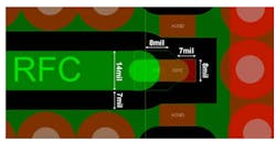
The RF transmission lines were designed using a coplanar waveguide (CPWG) model, with trace width of 14 mil and ground clearance of 7 mil for a 50-Ω characteristic impedance. The RF transmission lines are extended by 8 mil from package edge to the tapered line used for RF pin transition (Fig. 4).
4. The evaluation board’s RF transmission lines extended from the package edge by 8 mil to enable a tapered line used for RF-pin transition.
The ADRF5046 Reflective Silicon SP4T Switch is priced at $71.91 each (in 1000-piece lots); the ADRF5046-EVALZ costs $499 (single piece).
