Troubleshooting a dead ceiling fan is pretty straightforward. It’s a little more frustrating when the fan has an RF remote control. New batteries in the remote are the first thing. This old Casablanca fan remote used A23 size 12-V batteries, like many garage-door openers. The LED on the remote would work, so the remote transmitter was not likely the problem.
Next is to remove the wall plate on the variable-speed switch. I confirmed there was ac going to the switch and bypassed it with a direct connection. Next was to take the housing off the fan and measure that the ac voltage was actually reaching the fan. Since the fan had power and the remote transmitter seemed to work, it was time for a teardown.
Teardown Time
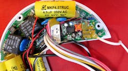
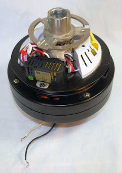
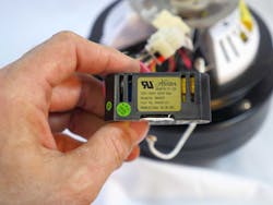
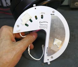
The inside of the fan had an electronics package above the motor (Fig. 1). There was a circuit board covered with a plastic cover, and a mystery black device similar to a relay (Fig. 2). The black unit, made by Hunter, turned out to be a current-limiting device for the lights that are part of the fan assembly. It prevents users from putting in lamps with too much wattage. This device will cycle the lamps off until you screw in lower-wattage units. Since the light is controlled by an SCR on the remote-control printed circuit board (PCB), it’s important to make sure the SCR current rating is not exceeded.
1. The Casablanca Claremont model 49G45H ceiling fan is rated 120 V, 60 Hz, 1.83 A, and 220 W. This model is a remote-control unit, hence the large and complex circuit board on the top of the motor. Hunter bought out Casablanca many years ago.
2. The fan has a model 98480X 300-W current limiter made by Hunter. This is in series with the light bulbs, which are controlled by an SCR on the PCB.
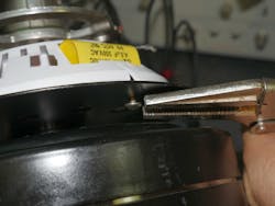
The disassembly procedure was abominable. To get the PCB removed, you have to use Vice-Grips to ease out the screws that are blocked by the motor (Fig. 3). The metal plate is captivated by the cast aluminum hanger; it does not come off the shaft, at least not in any easy straightforward manner. The screws are redundant to plastic clips that protrude through the plate. Engineers may have added the screws later, when the clips proved to be inadequate.
3. The mechanical engineering on the fan is a bit dismal. The only way to get the circuit board out is to use pliers to remove the two mounting screws.
Sketchy Engineering
A third redundancy retaining the PCB is double-faced-tape (Fig. 4). One real concern is that the aluminum heat-sink plate for the SCR is not insulated to the SCR, so it has ac voltage on it. That means the one strip of double-faced tape spaces the heat sink from the metal plate of the fan. While inaccessible screws are a bit lame, gluing your product together with tape is a bad idea and using the tape as an insulation system is even worse.
4. The underside of the PCB housing has a heatsink for the lamp SCR. It’s not isolated, and they use a piece of double-sided tape to space the heatsink from the metal fan housing.
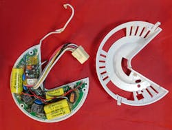
Opening up the PCB housing displays more questionable mechanical engineering (Fig. 5). The top housing is captivated by the connector that passes through it. You can see the only way to get the top off was to cut it so that the wires could be slipped by. Otherwise you would need a pin extractor made for this particular connector to remove the housing and let the wires pass through the narrow slot.
5. The large connector captivates the PCB top housing. You can see where I cut the housing to get the wires out. There are two black relays that control fan speed, and a white relay that changes the fan rotation. The large yellow film capacitors are for motor run, as well as motor speed control.
Figuring Out the Schematic
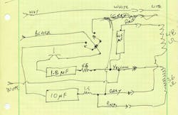
Ceiling fans are capacitor-run single-phase induction motors. This would explain at least one of the bright yellow capacitors on the PCB. There were also two black relays and one white relay. To reverse-engineer the circuit, make a diagram of the component locations so that you can make connections as you buzz the circuit out with a voltmeter (Fig. 6). The white relay was double-pole double-throw (DPDT), which is used to reverse the polarity on one of the fan windings. This is how the unit reverses the fan rotation. I did not bother to draw that relay or buzz it out; I was more interested in the capacitors.
6. To figure out the circuit, draw the parts in the same physical relation as on the PCB. Not shown is the white relay that reverses polarity of one motor winding to change the fan direction.
Once you have a layout with the connections, you can redraw the schematic more in line with good practice—inputs on the left, outputs on the right (Fig. 7). Even in this rough shape, you can see the series capacitor that connects with one of the motor windings. This capacitor changes the phase of that leg, to make the rotating magnetic field needed in an induction motor.
7. A schematic should show the scheme of the circuit, not the physical location of parts. So now rearrange the components so inputs are on the left and outputs on the right, with a sensible flow.
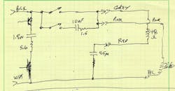
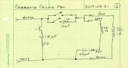
One final redraw makes the schematic more readable yet (Fig. 8). Now it’s clear where the motor connector goes to the two windings, and how the two black relays switch the fan on directly, or switch the fan on with a 10-µF capacitor in series to lower the speed. That 10-µF cap is realized by two 5-µF capacitors in parallel.
8. One more redrawing of the schematic makes it even more readable. Schematics are a visual language, and while there are many legitimate styles, a good schematic should be clear and obvious to most engineers.
I’m less sure of the 1.8-µF shunt capacitor controlled by a TO26-packaged SCR on the board. It’s obvious it shunts power away from the motor, so I have to believe it’s how the fan can have three or even four speeds. The series resistors on the 1.8- and 10-µF capacitors are likely to reduce contact wear and SCR inrush. They would also limit capacitor current when the controller happens to connect the caps at peak line voltage of 170 V.
“Fanning” the Flames…Almost
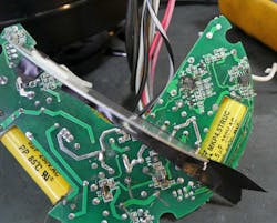
I blew up a few traces when I forgot to remove power while soldering a test point onto the PCB (Fig. 9). This is pretty lame in general, but when the PCB has lethal voltages, it’s really pathetic. I was soldering to the SOT23 transistors that operate the relays. I did verify that the 24-V power supply in this area was working, at least until I blew it up. I also managed to jump over the transistors to operate all three relays. I was going to “touch up” one bus wire, which I had soldered poorly, with my Metcal when the smoke and fire happened. This sad event made me give up on trying to figure out what was wrong with the remote circuit. I jumped the one relay that turns on the fan and resigned myself to just using the wall switch to run the fan.
9. Disaster strikes. I left the PCB plugged into wall power when I went to touch up a test point wire I soldered onto the transistor driver for the relay. In case you are wondering, Metcal irons have a nice earth ground that makes a nice black divot, which is at the top left of the right-hand yellow film capacitor. The heat-sink plate for the lamp SCR was riveted to the TO220 transistor. I had to bend it out of the way so that I could buzz out the circuit board.
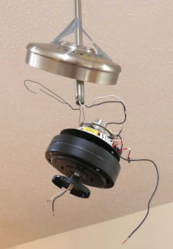
The most difficult thing was re-hanging the fan (Fig. 10). I had to work from the bottom of the mounting rod—the fan is installed on a very high cathedral ceiling and I could not reach the box in the ceiling and take down the entire fan. I hung the fan with some bailing wire, soldered a jumper to the ac line, and used the jumper to drag the ac wires through the fan mount and out a small hole in the side of the rod. Then I could screw the fan onto the mounting rod.
10. Working from the bottom of the fan mounting rod was a real treat. I used bailing wire to hang the fan from the rod. I threaded a black jumper wire through the fan center rod and soldered it to the ac input line. Next is to lube the wires with a little TriFlow and work the ac wires into the fan center rod. Then remove the bailing wire and screw the fan into the mounting rod while keeping tension on the ac wires. Then wire nut the line and neutral to the fan as well as the lamp wires you see hanging from the bottom of the fan.
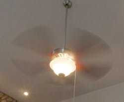
The fan now works like a champ (Fig. 11). I bought a switch for the light and wired it to the lower fan housing. The multi-speed wall control is a transformer/choke type unit. Other wall controls work by switching in capacitors, similar to the way this remote control changes fan speeds by switching in capacitors. The transformers and capacitive units change the phase between the voltage and current sent to the fan, reducing the power and hence the fan speed.
11. Success. The fan no longer has a remote control, but it works just fine from the wall switch. I added a pull-cord switch for the lamp. I did not wire in the Hunter lamp current limiter since there’s no need to protect an SCR that’s no longer used.
Testing the Remote Transmitter
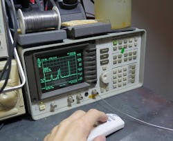
After all this, I wondered if my real problem was that the remote transmitter was not working, despite its LED shining when I pressed buttons. I fired up my HP 8590A spectrum analyzer (Fig. 12). Paul Grohe, a Texas Instruments engineer who was hired and mentored by Bob Pease, once told me that you can think of a spectrum analyzer as “just a radio that you can tune over a very wide range.” He also showed me that you can just stick a bus wire antenna into the input if you just need to see if there’s energy at some frequency.
12. I used my HP 8590A spectrum analyzer to see if the remote control was working. The right-hand peak pops up and jiggles when I press a button. It’s centered at 348.2 MHz. The remote-control receiver in the fan had failed, not the remote transmitter.
Since I did not care about the actual levels, just if there was some action, I did the bus wire trick. To my relief, when I pressed the remote buttons, I could see RF peaks popping up and modulating at 348.2 MHz, so I knew the remote was working. I did find a used remote PCB, but it was 120 bucks, and for that I would just buy a new fan. It looks like the remotes are hard to find. I will list mine on eBay, with that spectrum analyzer picture to show it works. Somebody should give me 10 bucks for it. That, on top of a repaired fan, is a nice reward.
