I have nine Garrity rechargeable flashlights. They plug into a wall socket to charge, and when power fails, the flashlight goes on, serving as an emergency lamp. What I love about this discontinued Garrity flashlight is that it uses AAA NiMH cells. When they get worn out, you can remove a single screw from the grip, and pop in three new battery cells. The flashlight is good as new. I also love that it is just small enough I can grasp it with my teeth, so I can use both hands.
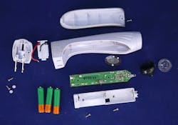
Recently, several of the flashlights would not properly turn on and off when I depressed the waterproof silicone switch button. Along with this problem, I noted that all of the flashlights have a leakage issue, so they emit a very dim glow when plugged in. A teardown was in order (Fig. 1).
1. The Garrity KE900 rechargeable flashlight will illuminate when power fails in your house.
Tearing into the Light
The construction was good—the screw that holds the grip and the four screws that hold the printed circuit board (PCB) and back housing are identical. There were two little white plugs over the screw heads in the back housing that holds the sliding plug, which you stick into your wall socket. A clear plastic lens was retained by a snap-in black plastic shroud that also held the LED. The nose of the flashlight was sonic- or solvent-welded to the body, which looks to be ABS plastic.
The component side of the PCB reveals a capacitive power supply (Fig. 2). This is where you use an X-rated capacitor to drop the wall voltage to a smaller value, without the need to waste power in a dropping resistor. There was clear plastic tubing around the capacitor, as well as a current-limit resistor and a large 47-µF capacitor. The capacitor sleeves were glued down, but not the resistor sleeve.
2. The component side of the PCB holds the power switch, plus red and yellow LED holders. The red LED lights when charging, the yellow LED indicates the flashlight switch is on, and the light will go on when power fails or you remove it from the wall socket.
The solder-side of the PCB has surface-mount resistors and a transistor, as well as the battery terminals that insert into the battery-holder housing (Fig. 3). The white LED is angled from the PCB, perhaps so the slightly longer leads can dissipate heat.
3. The solder side of the single-sided PCB has the terminals for the battery holder along with several surface-mount components.
The Switch Problem
The problem with the switch is a mechanical interference (Fig. 4). The silicone cover does not have enough clearance to let the push-push switch rise up adequately to cycle. After seeing the issue, I went to another flashlight with the same problem. By digging my fingernails into the side of the silicone cover, I could pry it up enough to hear that satisfying “click” that indicated the switch had cycled. This might be a manufacturing tolerance stack-up problem, or perhaps the silicone has absorbed water or oil and then swelled or deformed.
4. The silicon switch button is cut up to clear an electrolytic capacitor. The rubber has shrunk, so the push-push toggle button will not rise up enough to cycle. I might grind down the nub in the center of the silicone button to provide more clearance, or shave some of the plastic switch button down to fix things.
The black plastic surround on the silicone switch button is cut away to clear the electrolytic capacitor on the PCB. This had to be a last-minute fix and cried out for a reverse-engineering schematic effort. To figure out the schematic, I took a picture of the solder side. I used my IrfanView image viewer to increase the brightness of the image, so it was mostly washed out. Then I traced over the circuit traces with a red pen. I scanned that and used the printout to draw the components in blue (Fig. 5).
5. Here’s a picture of the PCB with brightness adjusted to wash out the darker areas. I traced over the traces with red, and then added the components in blue. I assigned reference numbers to the top-side components without realizing they are different from the silkscreen reference designators.
Deriving a Schematic
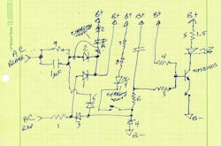
The layout let me draw an ugly schematic (Fig. 6). I knew it had to flow left to right, like any good schematic. I started with the LED output, and tried to work back to the left toward the input. I also knew to start drawing the input stuff on the left. Things get a little tangled up in the middle.
6. Working from Figure 5, a rough schematic is drawn up that’s correct, but hard to read.
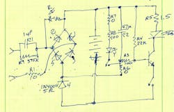
After a little staring, I realized there was a diode bridge in the middle, so I re-drew the schematic (Fig. 7). The extra diode, #4, is how the flashlight turns off when charging. When the flashlight is plugged in, diode 4 is forward-biased, which makes the emitter of the pass transistor rise relative to the base.
7. A quick re-draw of the schematic makes it more understandable. The key is diode D4, which drags the base of the pass transistor down to turn off the LED when the unit is charging, and both switches are thrown.
The low impedance at the cathode of D4 will overpower the 22-kΩ pull-up resistor R4 and shunt its current from the base of the transistor to the diode D4 cathode. When power goes out or you unplug the flashlight from the wall, diode 4 stops conducting, and its cathode goes high-impedance. Now R4 can supply current into the base of the transistor, turning on the LED. This is predicated on the switches being closed—both the contacts in the LED leg, and the switch that connects the small indicator yellow LED to show the flashlight will turn on at power failure.
No matter the position of the push-to-toggle switch, the red LED at the upper left will glow whenever the flashlight is plugged in. That’s because the ac input will drop below the battery positive voltage periodically and illuminate the red LED.
R1 limits the current inrush when you plug the flashlight into the wall. This is a serious problem with capacitive power supplies. It’s unlikely that you will make contact with the wall socket when the house voltage happens to be 0 V. Indeed, it might be up at 170 V, the instantaneous peak of 120 V rms ac power in the United States. That sudden 170 V will just sail right across the capacitor and appear at the side you want to be 5 or 10 volts. Most capacitive power supplies have a Zener diode to limit this voltage, whereas this circuit just uses the NiMH battery stack to provide the low impedance clamp.
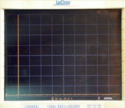
I rigged up my LeCroy scope with some math to do a differential measurement across the battery (Fig. 8). I plugged and unplugged the ac input a few times and got a several-hundred-volt spike that went off the display. This makes me suspicious. If there is only 170 V peak available, my LeCroy is showing over 200 V. I think it’s time to buy a differential probe and report back.
8. Plugging the capacitive power supply into the wall right when the voltage is at its 170-V peak means that spike travels across the capacitor and appears at the battery pack. This spike shows over 200 V, which might be an anomaly in the scope or my setup—it’s hard to believe the spike is this big. I’m buying a differential probe to find out for sure.
Another Design Issue
The other design issue I see is the way the holdup capacitor C2 is wired. Both R7 and R6 are 0-Ω resistors used to allow a circuit trace to pass underneath. This enabled Garrity to use a cheaper single-sided circuit board. The problem is that with R6 being 0 Ω, the capacitor is trying to filter the very low impedance of forward-biased diode D4. It would make more sense to have R3 be 0 Ω and R6 be 100 Ω. If R6 is 100, that would mean R8 should be zero to keep the yellow LED the same brightness.
Even 100 Ω seems like too little. Let’s say the battery runs at 3 V, but the charging system pulls it up to 4 V. That’s not exact, but this is analog. So, if you have 4 V and you want to keep the base of that transistor around 1 V, where the emitter is sitting during charging, that means there’s 22 kΩ across 3 V. Therefore, a 7.3-kΩ resistor at R6 should be able to keep the transistor from turning on, if there was no yellow LED to worry about. If the yellow LED leg is wired to a switch that went to the bottom side of R6, voilà, that seems to solve everything. That’s essentially the way it’s wired now, only through the 0-Ω R6.
With R6 being 7.3 kΩ, that would mean the electrolytic capacitor C2 could be much smaller, perhaps even ceramic or film type. It’s needed since the ac waveform does cross zero 120 times a second and you don’t want that modulating the transistor. Heck, even if R6 is 1 kΩ, it means the capacitor can shrink, and that might mean it fits under the silicon button. I have to believe my problems with the button not clearing the switch might be due to the fact Garrity had to cut that black plastic rim out to clear the electrolytic capacitor C2.
Well, it looks like it’s time to hit SourceESB or one of the distributors to get some resistors and capacitors to play with. I also wonder if instead of a diode bridge, I could set up a plus-minus output that would turn off the LED when charging. That would mean two 1N4004 diodes instead of five. Every engineer loves a cost reduction; I will let you know what I learn.
Some Good Reading
Microchip has an app note about capacitive power supplies. It says the shunt resistor across the capacitor is to reduce EMI, but I’m pretty sure it’s really to discharge the capacitor when you unplug the power supply from the wall. Also STMicro has a little buck regulator chip that you can use in place of a capacitive supply. It’s good for over 5 W, so it might be overkill for this low-power flashlight charger. And the fine folks at Power Integrations make a chip that discharges the capacitor, but only when power is dropped. This saves the constant power loss of that hardwired bleed resistor R9. Mouser has a nice write-up by TDK about capacitive supply design.
Meanwhile, the problem with the switch, that fat electrolytic capacitor, and the dim light leakage when plugged in might explain why Garrity pulled this model from the market. I still love them, though, and hope to keep these working for long time.


