Modeling on Mondays: Nonlinear SPICE Models of Vacuum-Tube Triodes (Part 3)
What you’ll learn:
- Given appropriate models for vacuum tubes, circuit simulators such as SPICE make analysis based on such nonlinear models a tractable effort.
- The Langmuir, Leach, and Koren models are discussed for the best fit to real-world 12AX7 device data.
In a recent article,1 we visited the triode vacuum tube (VT) and gathered the basic tools needed to model VT-based circuits. SPICE―in particular, LTspice―is our simulation tool of choice.
We relied on the classic gm equivalent circuit to model the triode itself, using the 12AX7 as an exemplar, and we noted the limitations of the gm model. That model generally works well in describing a circuit’s operation under small-signal ac conditions. Also evident, though, from its characteristic curves is that the 12AX7 (as is the case with all VTs) is essentially a single-quadrant device, just like FETs and BJTs. Its plate current and plate voltage are both non-negative. And there’s nothing linear looking about the plate curves themselves.
The next meaningful step is to consider some nonlinear models for the triode.
Langmuir and Leach
De Forest had a poor understanding of even the basic operation of his triode Audion. The Audion was unreliable, and it performed poorly because he thought it required a partial atmosphere within its envelope so that ionization would occur. But the efforts of Harold Arnold of Western Electric and of Irving Langmuir, an expert in high-vacuum technology, showed that a hard vacuum should be employed to avoid voltage-related breakdown and increase the Audion’s current gain.
Another early contribution from Langmuir was the development of a theory that describes, based on physical principles, and under a particular set of assumptions, a 3/2-power relationship between plate current and plate-to-cathode voltage in a vacuum diode. The assumed extension of the Langmuir-Child law to the vacuum triode states that the plate current iP is:
iP = KP (µvG1K + vPK)3/2 , µvG1K + vPK ≥ 0 (1)
where KP and the amplification factor μ are constants particular to the VT being described.
Analysis of VT-based circuits via circuit simulators such as SPICE began in earnest in the mid-1990s, as models other than the small-signal ac model were being investigated, developed, and used. Rydel’s paper2 was perhaps the earliest of consequence, followed shortly by a paper by Marshall Leach3 that’s now treated as a classic.
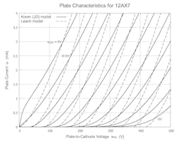
Leach’s model employs the extended Langmuir-Child 3/2-power law, as given in Equation 1 for vG1K ≤ 0, adding to it a series combination of diode and resistor in the grid-cathode leg to account for the fact that grid current flows when vG1K > 0. Figure 1 depicts the set of plate curves obtained when Leach’s simple two-point method of setting values for KP and μ is used in associating the Langmuir-Child equation with the published 12AX7 curves.
When comparing the set of curves generated by the Leach model with those in the datasheet for the 12AX7, you see it’s quite evident that the Langmuir-Child equation doesn’t provide a particularly admirable fit. In fact, just compare the Leach curves with those of the Koren model in the same figure. The Koren model, it turns out, provides a very good fit to the curves of the 12AX7 datasheet’s bogey tube.
Koren’s Model
The basic model developed by Norman Koren4 in the late 1990s for triodes is one deserving attention, even today. It is a phenomenological model—i.e., its structure and the parameters involved are chosen so that a good fit can occur, but without necessarily relying on governing physics. This type of model, sometimes called a compact model, is not uncommon for SPICE models of active devices.
Koren’s model as applied involves seven parameters (including a resistance that’s involved only when positive grid current flows, and the contact potential, which has been separated out from the total grid-to-cathode voltage). Koren has pointed out that he didn’t spend a lot of effort on modeling the triode’s action for vG1K > 0; that region of operation still isn’t well understood. There are, however, applications in which VTs operate temporarily within that region.
Fitting the model well to a particular VT’s plate curves is, of course, the sizable and important step. Finding an appropriate optimization routine―or writing one’s own―can end up a daunting task. However, descriptions of approaches are readily available on the web.
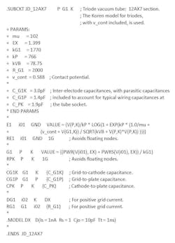
An alternative is to write a routine that overlays the published plate curves with the curves from the VT model and allows the user to adjust the values of the model’s parameters until a good fit is obtained. Dimitry Nizhegorodov has gone that route; he made his Java-based model paint kit5 freely available. Figure 2 depicts the listing of .SUBCKT JD_12AX7. It gives parametric values, including those of the inter-electrode capacitances, used for the Koren-model-based results given herein. Nizhegorodov’s model paint kit was employed.
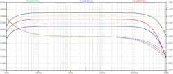
Figure 3 shows the frequency response under small-signal conditions for the basic common-cathode gain stage, whose schematic is depicted in Figure 1 of Reference 1. The simulation results when the small-signal ac model was used for the 12AX7 were shown in Figure 2 of Reference 1, and they appear in Figure 3 herein as the green curves.
The other two sets of curves―the blue, generated by the Leach model, and the red, generated by the Koren model with the parametric values given in Figure 2―are similar, with the main distinction being differences in midband gain.
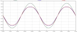
Figure 4 shows the simulated output in the time domain according to each of the three models investigated. The input signal is a 1-kHz sinusoid of amplitude 1 V. That amplitude was chosen because, from the plate curves on the 12AX7 datasheet, and for the Q-point chosen, a 1-V input should drive the VT near the edges of its normal active region. Also, distortion in the output waveform should be noticeable but not severe.
Indeed, distortion is evident in the waveforms associated with both the Leach and the Koren models. The output waveform from the small-signal model is as expected—it appears to be a perfectly good sinusoid. After all, the small-signal model is linear; it knows nothing of boundaries of an active region.
Upon observing the waveforms, it might be evident to you that the Leach and Koren outputs have both even- and odd-harmonic distortion. LTspice can confirm that observation by finding the Fourier components, and from that information we can obtain the harmonic distortion.
From the simulation producing Figure 4, we find that, for the Leach model, the output has a total harmonic distortion (THD) of 4.2%, with second-harmonic distortion prevailing at 3.7%. The Koren output has 6.1% THD, with third-harmonic distortion prevailing at 5.7%.
Now What?
What more can be done? One choice is to play further with simulations. Three distinct models of a 12AX7 have been touched upon―the linear, small-signal AC model in Reference 1, and the two nonlinear models herein. Another choice is to build the circuit, make some measurements, compare what you see on the bench with what the simulations say, evaluate your findings, and then judge whether the “best” of the models being considered is sufficient. If not, decide what you want to do about it. This is largely what modeling is about!
Parting Thoughts
Several other VT-modeling efforts besides those of Koren are available to learn from. Ayumi Nakabayashi’s efforts should be given serious consideration.6
We’ve restricted our brief familiarization with VT modeling to that of triodes. Triodes have shortcomings, and it was the subsequent introduction of additional elements within the tube’s envelope that improved the VT’s performance, especially at higher frequencies.
A tetrode results with the addition of a second grid—the screen grid—situated between the control grid and the plate, which breaks up the grid-to-plate capacitance of the triode. Such capacitance can result in severe bandlimiting through the Miller effect. Plus, gm increases substantially due to the additional grid being held at a positive potential with respect to the cathode. But the inclusion of that screen grid can also result in a generally unwanted negative-resistance region of operation appearing at low plate-to-cathode voltages.
Adding a third grid (a suppressor grid), situated between the screen grid and the plate, saves the day by capturing most of the secondary electrons thrown off the plate due to the increased acceleration provided by the screen grid. An alternative to this three-grid pentode is to substitute beamforming plates for the suppressor grid. Tubes of such construction are typically called either beam power tubes or kinkless tetrodes. The modeling efforts of Koren, Nakabayashi, and several others have extended to tetrodes, pentodes, and pentode-like VTs. Those models are, of course, more involved.
References
1. Stephen A. Dyer, “Simulation of Vacuum-Tube Triodes in SPICE: An Introduction (Part 1),” Electronic Design, Nov. 18, 2024.
2. Charles Rydel, “Simulation of electron tubes with Spice,” preprint, Audio Engineering Society 98th Convention, Paris, Feb. 1995.
3. W. Marshall Leach, Jr., “SPICE models for vacuum-tube amplifiers,” J. Audio Eng. Soc., vol. 43, no. 3, Mar. 1995, pp. 117-126.
4. Norman L. Koren, “Improved vacuum tube models for SPICE simulations. Part 1: Models and example,” updated Mar. 20, 2003.
5. Dimitry Nizhegorodov, “Model Paint Tools: Trace Tube Parameters over Plate Curves, Interactively.”
6. Ayumi Nakabayashi, “Ayumi’s Lab.: Audio.”
