Latest from Analog

ID 217230663 © Christian Offenberg - Dreamstime.com | electronica.de
promo_messe_munich__id_217230663__christian_offenb
ID 312689142 © Chechotkin | Dreamstime.com
LiDAR in autonomous driving
ID 39977536 © Pino Carboni | Dreamstime.com
Transformers on a PCB
ID 326211957 © Kwangmoo | Dreamstime.com
Security IP CCTV camera using solar energy
Dreamstime_svetlanadiacenco_325233820 and LEM
dreamstime_svetlanadiacenco_325233820_promo
ID 22286147 © Piotr Adamowicz | Dreamstime.com
syntaxerror_dreamstime_l_22286147
Promo Ti 237024 5f6cbee5045c8

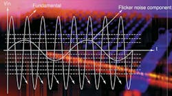
Measuring ADC Linearity from a Sine-Wave Input (.PDF Download)

Sept. 24, 2020

To obtain the transfer function of an analog-to-digital converter (ADC), it’s intuitive to feed a ramp signal and observe the ADC output code. But the greater the resolution and precision of the ADC, the more complex it becomes to generate the ramp signal.

For example, let’s consider an 18-bit, 1-Msample/s ADC, where the transfer function must be measured at 1 LSB/16 = 0.0625 LSB (for hits per code = 16) precision. This means that the ramp signal should be stepped at 0.0625LSB; thus, the resolution of the ramp-signal generator should be 22 bits. However, this is severely limited by the DAC chosen for the ramp generation. And when considering the DAC’s nonlinearity, this doesn’t seem like a practical solution.

Comments

To join the conversation, and become an exclusive member of Electronic Design, create an account today!