Courtesy of Micro-Measurements
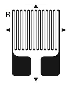
Many conventional strain gages are similar in appearance to Figure 1. A serpentine pattern etched into a metal foil creates a relatively high resistance in a small space. The foil is bonded to a thin insulating substrate, which the user bonds to the structural element being measured. For example, to measure bending in a metal bar, the long lines of the serpentine pattern should be parallel to the length of the bar. The gage in Figure 1 includes small arrows in the foil pattern to assist alignment.
This type of strain gage changes its resistance when stretched or compressed. The variation is small so some form of amplification is required. Traditionally, a Wheatstone bridge circuit has been used together with a suitable indicating meter. Modern bridge amplifiers are based on this technique. However, there are other approaches that offer further noise reduction and improved immunity to temperature effects.
When connected to a strain-indicating instrument, the output of the gage has units of “strain” or more usually “micro-strain.” These dimensionless units represent the change in length divided by the original length (∆L ⁄ L) caused by deformation of the substrate and the attached gage. For example, 1.0 µ-strain could correspond to 1.0-µm deformation per meter of length or 1.0-µin. per inch of length. The measurement of 1.0 µ-strain indicates the same amount of strain regardless of the dimensional units.
The gage factor FG is defined as the relative change in resistance caused by the relative change in length
∆R ⁄ R
FG = _________
∆L ⁄ L
and typically ranges from 2 to 5 for metal foil gages. A high FG value corresponds to a more sensitive gage. Almost all of a gage’s resistance is contributed by the long, thin pattern elements. However, a close look at Figure 1 shows thickened areas where the pattern bends. Thickening these parts helps to minimize the gage’s sensitivity to strain in the right-left direction—it’s so-called transverse sensitivity Kt. Nevertheless, all gages do exhibit a Kt as well as temperature dependencies.
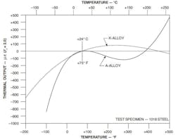
Typical gages are made from constantan (A alloy) or Karma (K alloy) foil. As shown in Figure 2, the effect of temperature is minimized in self-temperature-compensated gages. Achieving performance like this is not straightforward because virtually all of a strain gage’s parameters are affected by temperature changes. A potentially large error can result from incorrectly matching a gage and the material onto which it’s going to be bonded.
Courtesy of Micro-Measurements
A Micro-Measurements technical note1 explained that the manufacturer’s self-temperature-compensated strain gages are available in several thermal expansion coefficient versions. For example, the expansion coefficient of gray cast iron is 6.0 ppm/°F. A gage that’s going to be bonded to a cast iron part should have a matching thermal expansion coefficient to minimize thermal effects. For Micro-Measurements gages, the coefficient is indicated by a two-digit “S-T-C” code—06 for a gage to be bonded to cast iron.
A range of S-T-C codes is available—09 for copper, 13 for tin, 03 for tungsten, 15 for magnesium, and 30, 40, and 50 for plastics. As the technical note stressed, the highest accuracy is achieved by measuring the gage on a piece of the actual material being used in the test. Several factors are involved.
The polynomial equation describing a gage’s temperature sensitivity is based on the average performance of a production batch of similar gages. So, the behavior of any one gage will differ somewhat from that average. And, as the technical note explained, “… the thermal output data given in the gage package were necessarily measured on a particular lot of a particular test material. Different materials with the same or closely similar nominal expansion coefficients, and even different lots and forms of the same material, may have significantly different thermal expansion characteristics.”
In fact, because of the wide variation in the characteristics of some types of plastic, Micro-Measurements gages with high S-T-C codes actually are calibrated on 1018 type steel substrates. The technical note includes equations and examples that allow a user to calculate the strain when a gage is bonded to a material different from the one originally used to measure the gage output.
Gage excitation and measurement
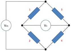
As shown in Figure 3, the Wheatstone bridge circuit, traditionally used with strain gages, is deceptively simple. Before any measurements can be made, the bridge must be balanced. Ideally, all four elements would be identical in every way—value, temperature coefficients, aging characteristics, etc. And, the exciting voltage source should be free of noise and have perfect compliance regardless of load changes.
Practically, some of the resistances will be strain gages, ideally from the same manufacturing batch, and some will be precision fixed-value resistors. The number and relative positions of the strain gages determine the type of measurement being made.
Before self-temperature-compensating gages became readily available, it was common practice to use a compensating gage to offset the extraneous errors generated by another gage (the measuring gage). If the measuring gage is in position 1 and the compensating gage is in position 2, then assuming the same resistance errors are developed in each gage, the midpoint of the bridge won’t be affected—the errors cancel.
In addition to using two gages, this method requires that the compensating gage undergoes exactly the same environmental conditions as the measuring gage while at the same time experiencing no strain. Accurately achieving this condition may not be practical. Because only one gage actually is measuring strain, this method is called a quarter-bridge with a compensating strain gage.
Applications such as a bending beam can use two measuring gages to advantage: one on the top of the beam and the other directly below on the bottom of the beam. The two measuring gages are connected in positions 1 and 3 so that the bridge output signal is doubled. Each gage must be compensated in the same way as the quarter-bridge circuit. Although four strain gages may be used, only two are measuring strain, so this is called a half-bridge circuit.
A full bridge, in which all four gages are measuring strain, according to an HBM strain gage handbook, most often is used “… in transducers and related measuring techniques.” Because all four gages are mounted very close to each other in most applications of this type, the interconnecting leads are short and have little influence on thermal performance. This is not the case in quarter- and half-bridge configurations in which the interconnecting leads must be treated in specific ways to reduce thermal errors.
In all simple configurations, the voltage drops across the leads connecting the bridge to the excitation source subtract from the source and reduce the effective gage factor. This is the same kind of problem that is encountered in any two-wire resistance measurement, which can be solved by adopting four-wire (Kelvin) techniques.
Selected Products
HBM
HBM bridge amplifiers such as the QuantumX Series MX1615B Bridge/Strain Amplifier use the patented Kreuzer circuit to eliminate voltage drop errors in quarter- and half-bridge applications. An extended version of the circuit connects to each gage with four wires—two carrying current and two sensing voltage—and allows the completion resistor to be located in the measuring instrument up to 1,000 meters from the gage. An article on the HBM website discusses how this measurement technique was used with 150 strain gages positioned on the body of a railway passenger coach undergoing static and dynamic load testing.
Ravi Shukla, QuantumX/SomatXR business development manager at HBM, said that many of the company’s 24-bit modules “… provide AC and DC excitation to offer flexibility when choosing the appropriate excitation to limit signal noise. In addition to the hardware advantages, the HBM catman software interface was developed to provide easier component setup with integrated strain gage analysis features including a live FFT, strain gage Rosette Analysis, and many user-configurable plotting capabilities.” Using AC excitation for dynamic applications has the advantage of eliminating slowly changing thermal errors.
Precision Filters
Precision Filters takes a different approach to gage excitation, using the company’s proprietary balanced constant current (BCC) technique. As described by Alan Szary, vice president, engineering and business development at the company, “Precision Filters makes a distinction between bridge conditioning and strain gage conditioning. Often, a strain gage measurement is made using the well-known quarter-arm Wheatstone bridge configuration. For many strain gage measurements, this is not the correct method and could result in measurement inaccuracies and increased noise levels.
“Precision Filters’ strain conditioning cards employ our proprietary BCC technology.” He explained, “BCC technology excites the strain gage using constant current rather than constant voltage excitation, eliminating measurement inaccuracies related to lead wire resistance. The high level of impedance balance of the input circuit, combined with excellent CMRR of the diff-amp stage, results in a high degree of rejection from noise pickup from external electrostatic noise sources.”
In addition to lower noise, the BCC approach provides a large and bipolar voltage compliance range. It also supports injection of an AC test current that allows verification of gage, cable, and system frequency response. BCC technology is used in the company’s 28000 System with 64 channels of dynamic strain conditioning and in dynamic strain conditioning modules compatible with the National Instruments CompactRIO platform.
National Instruments
NI’s product range includes the eight-channel PXIe 433x Series bridge input modules, and for CompactDAC or CompactRIO applications, the multichannel 923x Series bridge strain modules. As explained in the NI PXIe 4330/4331 user manual, “Remote sensing corrects for resistances from the [excitation] EX leads on the NI PXIe-4330/4331 to the sensor, and shunt calibration corrects for these errors and for errors caused by wire resistance within an arm of the bridge. Shunt calibration is most useful with three-wire quarter-bridge sensors because there may be significant resistance in the wiring to the sensor and remote sense cannot be used.”
The manual continued, “Shunt calibration involves simulating the input of strain by changing the resistance of an arm in the bridge by some known amount. This is accomplished by shunting, or connecting, a large resistor of known value across one arm of the bridge, creating a known change in the bridge output. You then can measure the output of the bridge and compare it to the expected bridge output value. You can use the results to correct gain errors in the entire measurement path or to simply verify general operation to gain confidence in the setup.” A 100-kΩ resistor is used in the NI modules—a large enough value that the resistance of leads connecting the shunt resistance is negligible in comparison.
Data Translation
Also capable of handling full-, half-, and quarter-bridge circuits, Data Translation’s DT9838 USB module features simultaneous sampling with 24-bit resolution across all four channels. A tachometer input is provided as well. Because strain gages are the building blocks for transducers such as load cells, torque sensors, and pressure sensors, these bridge-type devices also can be attached to most bridge amplifiers. Many of these products have a full-bridge configuration so no additional completion resistors are required.
The excitation voltage is programmable from zero to 10 V in 167-µV steps, and bridge completion resistors can be selected by software to complement quarter- or half-bridge connections. A sync bus is provided that allows up to four DT9838 modules to be synchronized. Finally, software calibration of the bridge offset and gain is provided.
Yokogawa
Yokogawa’s DL850E ScopeCorder accepts both type 701270 and type 701271 strain modules, the main difference being the type of input connector. The 701271 with a nine-pin D-sub connector has enough pins to support shunt calibration. Both modules feature 16-bit ADCs compared to 24-bit resolution used by some other manufacturers. However, the importance of the apparently large difference depends on the noise levels exhibited by these and competing bridge amplifiers.
Interestingly, where some other amplifiers use a fixed 2.0 gage factor—Micro-Measurements metal foil strain gages have a 2.0 gage factor—the Yokogawa modules provide a gage factor variable from 1.90 to 2.20 in 0.01 steps. Gages with 120-Ω resistance are supported for only 2-V excitation. Higher resistance gages can be used with 2-V through 10-V excitation. For either type of module, an auxiliary bridge head (Model 701957 [120 Ω] or 701958 [350 Ω]) is needed to accommodate separate strain gages and completion resistors.
United Electronic Industries
Although United Electronic Industries manufactures the DNx-AI-208 eight-channel low-cost strain measurement board with 1-kS/s sampling rate and the high-performance DNx-AI-224 strain measurement board with 100-kS/s sampling rate, the DNx-AO-358 strain gage simulator board is unique among the three products.
Bob Judd, director of marketing at the company, said, “… [The AO-358] has been used in a variety of applications, including simulating rudder pedals on a military flight trainer, simulating the air-lock monitoring interface on the International Space Station, and testing other strain gage input devices.”
Judd elaborated: “A big reason why customers select UEI as their solution is related to other aspects of the measurement system beyond strain gages. UEI’s capability to distribute the system over Ethernet and even fiber makes it easy to use our hardware in widely distributed applications like those you would find in civil engineering projects such as bridge monitoring and building frame monitoring.”
Elsys
“Bandwidth and precision make Elsys stand out,” according to Klaas Vogel, consultant at the company. He said, “Elsys handles event speeds with rise times of 0.2 µs or equivalent to 1.5-MHz bandwidth. Its differential amplifiers to which the strain gage signals are delivered feature better than ±0.1% precision.”
The SGA-2 strain gage amplifier handles quarter-, half-, and full-bridge configurations and features four- and six-wire connections that eliminate wiring voltage drops to and from the excitation source. The amplifier’s 50-Ω output impedance is matched for connection to an Elsys transient recorder or to a third-party DAQ system.
Graphtec
The four-channel GL7-DCB strain amplifier module is intended for use with the company’s Model GL7000 DAQ platform—“the industry’s latest standalone strain gage monitoring system that does not require a PC,” according to Ken Matsunaga, senior sales manager for instruments. Similar to Yokogawa, this Graphtec module also has 16-bit resolution. However, the gage factor is fixed at 2.0, limiting use to metal-foil gages.
ADC resolution is more than sufficient in those modules using 24-bit converters. However, these devices use sigma-delta (∑∆) technology, which means that they can exhibit a significant latency. In addition to typically having a lower bandwidth than successive approximation or flash converters, ∑∆ converters may delay their output by a number of conversion cycles, which could be important if a strain gage were part of a real-time feedback control system. ∑∆ converters with so-called zero-latency still have a delayed output, but the amount of delay is less than one output sample period.
The GL7-DBC includes support for sensors that use transducer electronic datasheets, simplifying calibration. Anti-aliasing filtering also is provided with several corner-frequency selections and a -30-dB/octave slope.
Micro-Measurements
Micro-Measurements, a Vishay Precision Group brand, provides a large selection of strain gages as well as a range of strain-gage instrumentation products. The P3 Strain Indicator and Recorder is a portable instrument. The company’s 2100, 2200, and 2300 systems are multichannel analog bridge amplifiers with manual controls.
Recently, the 9000 High-Speed DAQ system was released to supplement existing slower speed 7000 and 8000 systems. Each of the 12 RJ-45 strain-gage inputs and four auxiliary inputs is processed in a 24-bit DSP with FIR filtering. As described in a press release, “The processors over-sample data at a rate of 128x the selected rate, providing high-quality, low-noise data at rates of 50,000, 25,000, 10,000, and 5,000 S/s without the need for signal averaging.”
In addition, a series of strain gages has been launched using the company’s Advanced Sensors strain gage technology. State-of-the-art equipment and tooling are used to provide tighter tolerance products with shorter manufacturing lead times. The new gages are especially important to transducer manufacturers that need “… tight tolerances, long-term stability, and high reliability [gages] that are readily available from stock or with short lead times at competitive prices,” according to the company’s technical sales manager Jim Johnson.
Additional information
Some distinguishing features have been noted for strain-gage modules from several manufacturers. A few observations apply to all the products. For example, although each product truly is a module, almost all have a proprietary form factor. If you are adding strain gage inputs to a PXI- or VXI-based test system, many of the products listed are not directly compatible.
Another factor is isolation. Strain gages end up attached to a wide range of things, often in challenging industrial environments. And, although the gage substrate insulates the foil from the item being measured, shorts do occur. In general, the instrumentation design must assume that the gage is not operating near ground potential, hence the 1-kV isolation quoted by several datasheets.
Sensitivity is yet another consideration. Increasing the bridge excitation voltage is the easiest way to boost the system gain, but doing so also increases the power dissipation in each gage and the associated self-heating. Is that a problem in your application? If so, the distributed amplification approach used by Precision Filters could be useful. As described by the company’s Szary, “… our distributed gain topology allows for the use of prefilter gain, for the lowest noise configuration, or postfilter gain, for use in harsh environments where extreme out-of-band noise is possible, such as shock measurements.”
Reference
- Strain Gage Thermal Output and Gage Factor Variation with Temperature, Tech Note TN-504-1, Micro-Measurements.
For more information


