Magnetic Sensors for All Seasons
What you’ll learn:
- The types of magnetic sensors that are currently available.
- How the magnetic sensors work.
- Applications for the different magnetic sensors.
Position sensors enable a variety of functions and controls in electromechanical systems. Historically, designers implemented these sensors with microswitches and potentiometers that detect motion within the system. However, moving parts in these components wear out over time, oxidizing and accumulating grime from environmental exposure. In this case, components can fail and cause system-level failures.
Contact-free sensing technologies are replacing mechanical solutions to increase product reliability. Most materials are permeable to magnetic fields, making magnetic sensors a convenient alternative to reduce mechanical points of failure.
Each type of magnetic sensor has advantages and limitations that can create uncertainty when selecting the proper sensor for an application. In this article, I’ll outline the functionality, benefits, and potential drawbacks to each of these technologies.
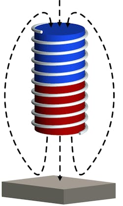
The discoveries of Michael Faraday led to the development of the variable reluctance sensor, which uses a wire-wrapped magnet to detect changes in the magnetic field (Fig. 1). The sensor requires a magnet large enough to be wire-wrapped and is often somewhat bulky, but it doesn’t require an external supply. The magnetic field is drawn toward ferromagnetic materials that induce currents in the winding as the field changes.
The variable reluctance sensor is often used to detect the speed and motion of targets such as reluctance rings in anti-lock braking systems (Fig. 2) or pickups on the strings of electric guitars (Fig. 3). The sensor output is current mode, so combining outputs from multiple sensors is simple.
Edwin Hall discovered an alternative approach to Faraday’s variable reluctance sensor that enables smaller sensors. The simple construction of the Hall-effect sensor results in a very small and cost-efficient device. Depending on the application, the magnet required can be quite small as well.
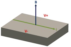
When a magnetic field is applied perpendicularly to the current through a conductor, the Lorentz force causes the development of a voltage potential across the conductor, which is orthogonal to both the current and the magnetic field (Fig. 4). Typically, these sensors detect field strength in the Z direction, but advanced 3D sensors can measure the total field.
Current is often forced in multiple directions through the conductor to limit offset and potentially reduce the sampling bandwidth. If sampled at full speed, a Hall-effect sensor also requires a continuously applied bias current.
Hall-effect elements are small, and they easily adapt to many applications. However, they require additional integrated circuitry to configure useful functions such as the switch, latch, and linear sensor. Switches toggle on and off with magnetic threshold crossings; latches require alternating polarities to switch output states; and linear devices vary their outputs with the changing magnitude of the input field.
>>Download the PDF of this article, and check out the TechXchange with similar articles and videos.
These configurations allow for the replacement of mechanical switches and contact wipers in many devices.
For example, some laptops use a microswitch built into the laptop hinge or a catch along the edge of the screen to detect a lid closure. Now, a magnet behind the screen bezel aligned to an accompanying Hall-effect switch, such as the TMAG5231 from Texas Instruments (TI), in the laptop body can serve the same function. The magnetic field activates the sensor when closed and produces an interrupt signal that sets the hardware into low-power mode.
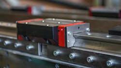
Three-dimensional Hall-effect sensors are useful in industrial applications. Figure 5 shows their use in measuring the linear travel of a shuttle along the track of an assembly line using angle calculations. Sensors such as the TMAG5170 can sense the composite magnetic field and provide a complete picture of the field vector to perform these more complicated angle calculations. Placed into an array, it’s possible to track multiple movers as they move goods through assembly lines.
Some magnetic fields are too weak to effectively measure with Hall-effect sensors alone. Magnetic flux concentrators focus the magnetic field across the sensing element, increasing the total flux by channeling the magnetic field through a ferromagnetic structure to where it can be measured.
This behavior is the fundamental principle behind how clamp-style current meters (Fig. 6) operate, which when miniaturized can be integrated into a semiconductor device. Such miniaturization can become a complicated procedure when attempting to optimize overall device sensitivity.
Concentrators work well when measuring fields that change in magnitude but maintain a constant direction, such as in current-sensing applications. However, the construction of the concentrator uses ferromagnetic materials that channel the magnetic field. Strong magnetic fields in magnetic concentrators can result in residual magnetization, which may cause hysteresis when changing magnetic states.
The implementation of an AMR sensor includes structures that change in resistivity as the angle of the incident magnetic field changes instead of measuring field strength. If the incident magnetic field is parallel to the direction of current flow in the material, the resistance remains unchanged. When the angle of incidence increases, the resistance will decrease to a minimum when the field is orthogonal to the current (Fig. 7).
AMR sensors configured into a Wheatstone bridge produce a sinusoidal output with two periods per revolution. While AMR structures require only a single process layer in semiconductor designs, the overall structure tends to be larger than the Hall-effect sensor.
The low noise and fast response time of AMR sensors make them great candidates to use for angle encoding in motors for the purpose of field-oriented control in high-speed systems.
Alone, an AMR sensor will resolve up to 180 degrees without aliasing, which limits its range in many rotation applications. But when combined with a two-dimensional Hall-effect latch such as TI’s TMAG6180-Q1, the quadrant output from the latch enables 360-degree rotation. AMR sensors can sample faster than Hall-effect sensors and offer significantly lower output noise.
TMR sensors typically comprise two magnetic layers separated by an ultra-thin dielectric layer (Fig. 8). When properly biased, electron tunneling can occur from one magnetic layer to another. An external magnetic field will impact how readily this tunneling may happen. Within the TMR sensor, one layer is pinned, while the other is free to be influenced by an external field. TMR sensors are sensitive to the direction of the magnetic field for a full 360 degrees.
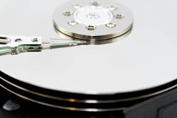
These sensors operate at very low currents and are the most sensitive to magnetic fields, which makes them common in the read heads of hard-disk drives (Fig. 9), low-power switching applications, and electronic compasses. Given their construction, TMR sensors may experience magnetic hysteresis and risk permanent damage when exposed to strong magnetic fields.
The discovery of giant magnetoresistance by Albert Fert and Peter Grünberg in 1988 earned the duo the 2007 Nobel Prize in physics, leading to the development of GMR structures. These sensors integrate several layers of alternating magnetic and nonmagnetic conductive materials. The specific layering of the magnetic layers enables variable resistivity through electron scattering caused by spin orientation.
GMR sensors can also measure the angle of the magnetic field for a full 360 degrees. GMR sensors aren’t as sensitive as TMR sensors, but they’re more sensitive than Hall-effect sensors. They’re also limited by a maximum field exposure. The previous state of the magnetic field may have some influence over the measured result, similar to TMR sensors.
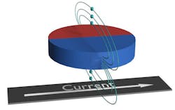
Inductive sensors operate with a magnet utilizing AC magnetic fields generated through an inductive coil sensor. The inductive coil is commonly routed using only copper printed-circuit-board traces. Connection with a capacitance creates an inductor-capacitor tank, which oscillates at resonance. When a conductor is brought near the coil, the field from the coil will induce an eddy current in the conductor (Fig. 10). This eddy current establishes mutual inductance, altering the resonant frequency of the coil depending on the range.
The design of the coil must match the capabilities of the analog front end driving and measuring the oscillations, but when configured properly, it’s possible to detect very small displacements. Inductive sensing isn’t affected by permanent magnets, which makes this technology useful in many pressure-, speed-, and angle-sensing applications. The effective range of the sensor is relative to the size of the coil and target conductor.
Devices such as TI’s LDC3114 include automatic baseline tracking, which compensates for environmental conditions and wear or damage to the target that enable the sensor to adjust over time.
Conclusion
The ability of magnetic fields to permeate most materials allows for systems to be designed with feedback controls in mind that simplify mechanical design challenges. They also provide critical information that can be processed and used to track various moving parts with real-time electronic feedback.
Because of this, each of the magnetic sensing technologies serves to drive innovation within the many devices that have become an essential part of daily life. As these technologies continue to advance and mature, the automated controls, safety features, efficiency, quality, and reliability of magnetic sensors enable smarter functionality and more sophisticated system control. Engineers who master the application of these sensors have a world of opportunity before them to imagine, innovate, and create.
>>Download the PDF of this article, and check out the TechXchange with similar articles and videos.
About the Author

Scott Bryson
Applications Engineer, Texas Instruments
Scott Bryson, an applications engineer with Texas Instruments' position sense product line, has 15 years of experience working in the semiconductor industry. He holds degrees in electrical engineering from both BYU (BS) and Arizona State University (MS). Scott currently specializes in magnetic sensing, but is also experienced working with current sensors, temperature sensors, audio amplifiers, and data converters.
