Getting Started With A Short-Range Radio Design
>> Website Resources
.. >> Library: TechXchange
.. .. >> TechXchange: Radio Design 101
Note: we are working to recover the figures for this article.
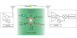
The process of designing a short-range radio system can be complex and often involves many project tradeoffs (Fig. 1). With a little insight, balancing these various characteristics—including frequency selection, one-way versus two-way systems, modulation techniques, cost, antenna options, power-supply influences, effects on range, and protocol selection—can make radio system design easier.
Selecting The Right Frequency
Why would a designer want to operate in the 868/915-MHz band rather than the 433.92-MHz part of the spectrum? In other words, how do you choose which frequency to use? Two primary considerations influence the answer: either the application has a traditional and/or predefined band in which it operates, or the designer must balance the tradeoffs of each parameter in the design to make the best band selection.
Commonly the most important parameter of a new design is meeting a targeted range for the system. Determining which band would be a better choice would be easier if the application had an unrestricted antenna size and placement, if the distance between radios were clear from obstructions, and if the units were wired to line voltage supplies. But if the application is a consumer product that must have an unexposed antenna, if its signal must penetrate walls in a home, and if its system needs to run for several years off of a coin cell battery, these tradeoffs become more important.
Physics indicates that radio signal range in open space is proportional to transmit power, antenna gain, and the square of the wavelength. Antenna gain and receiver sensitivity also are factors. Antenna size is inversely related to the frequency of operation, the lower frequencies requiring longer antennas.
In general, the lower-frequency bands provide better range capabilities and depend less on line-of-sight (LOS) communication, but in practice the other impacts tend to dominate the ultimate range obtained by the system. Parameters such as the antenna size and radiation pattern, true operating environment (fewer obstructions versus worst-case planning), and the noise impact from the application surroundings tend to have the greatest influence on the actual range of the system.
What about output power in these bands? How does it limit aspects like range or harmonics? The transmitter power can help compensate for other deficiencies in the system. However, this must be balanced by the restrictions imposed by regulating authorities (Part 15, CFR 47). It is very common to push the limits of the transmitter to make up for losses and inefficiencies in the antenna and matching system.
One-Way And Two-Way Systems
There still exists a broad range of applications that only require a one-way communication system. For example, actions like unlocking a car door or opening the window blinds in a house do not require any form of wireless feedback. As a result, there will always be a need for simple, cost-effective, one-way wireless communication.
Although a single-direction form of communication will likely always find a market, the need for monitoring, feedback, status display, and other user interactions is increasing. Thus, the one-way system may trend to a full transceiver arrangement. For example, in a remote keyless entry system, users may want to make sure their vehicle is locked. Or in the case of adjusting the window blinds in a house, users may want to know what the air temperature is at the window. These are both examples of a simple one-way technology that could migrate to a two-way application.
Modulation
The industrial, scientific, and medical (ISM) bands offer many styles of modulation. Designers tend to gravitate toward amplitude-shift keying (ASK) in the low bands (<470-MHz portion of the IEEE UHF band) due to its ease of use and because the hardware tends to be less expensive. Alternatively, frequency-shift keying (FSK) got a start in the low band with tire-pressure-monitoring system (TPMS) applications. It was found to be less prone to the detrimental effects of the application environment. (A rotating tire in a wheel well tends to cause amplitude modulation, or AM.) Any form of AM uses a linear demodulation method, so a good deal of noise gets through the system, while a frequency modulation (FM) system has better signal-to-noise ratio (SNR) with wider modulation (200 kHz on a standard FM channel). However, FM loses carrier lock quickly beyond a certain sensitivity threshold (waterfall).
FSK is used more prominently in the high band (>470-MHz portion of the IEEE UHF band) because of the need to meet tighter regulatory specifications. Running a frequency-base form of modulation allows the transmitter to operate as a CW signal, which cuts back on the kicking effects suffered from turning a power amplifier (PA) on and off (ASK or on-off keying (OOK). Upper frequency bands (>1 GHz, commonly L-, S-, and C-Bands as defined by IEEE) tend to use more sophisticated methods of modulation such as direct sequence spread spectrum (DSSS), mostly due to the overcrowding at those frequencies. This in turn necessitates better co-channel interference rejection.
Cost
Another driving force in ISM radio system design is the need for inexpensive yet reliable operation. Most ISM radios available on the market provide small integrated devices with few peripheral components and relatively small footprints. Available transmitters tend to be very simple—low pin-count circuits that require only rudimentary interfacing for the data to be transmitted, plus some minor impedance matching components and common decoupling capacitors.
Likewise, the receivers tend to keep the bill of material (BOM) component counts low, while still allowing enough flexibility for the system designer to make adjustments to meet the needs of a particular application. Printed circuit board (PCB) costs are reduced with small-footprint ICs, small BOMs, and no special requirements for more than two-layer stack-ups. Beyond the board and peripheral component cost, the only other external components needed are an antenna and a battery (for non-line-voltage systems).
Antenna
An antenna’s physical properties, such as type, size, shape, and orientation, can have a great impact on the design and effectiveness of a system. Since form factor can be a major constraint in any ISM application, these properties may dictate what frequency band is chosen and ultimately, which radio is used.
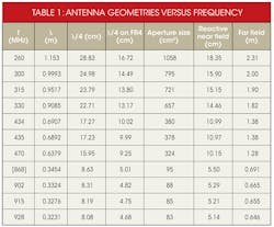
Antennas take many forms, from simple ¼λ monopoles and ½λ dipoles to loop, F, and others. They can also be categorized as E-field or M-field, depending on which form of current model they utilize. Antenna design can be an art form unto itself. The first step in selecting an antenna is to determine the largest dimensional length permitted within the constraints of the application and whether to use a “trace” or a physically attached antenna (Table 1).
Smaller antennas can be used efficiently in the higher frequency bands. However, there is an upper limit to this process. As the physical size of the antenna shrinks, so too does the aperture. A smaller aperture results in less energy being transferred from the antenna to the environment and vice versa. In antenna design:
- The dielectric material of a board will shorten the effective length of a trace antenna.
- Loop antennas generate a magnetic field while other “aerial” antennas generate an electric field.
- Magnetic antennas (loops) are less susceptible to the near-field environment (such as a user’s hand on a remote control).
- The antenna’s ground plane (counterpoise) distance and orientation can greatly impact the radiation pattern.
Power Supply
The methods and sources of powering the radio system can be as numerous as the applications in which they are designed. Common supplies include ac line voltage, car batteries (12 V) and 5-V automotive buses, lithium batteries (3 V), multicell alkaline batteries (1.5 V), rechargeable cells (1.2 V), energy-harvested sources, and more. In most cases, the transmitter is run from one source and the receiver from another (such as lithium cell in the TX, and 5-V automotive bus for the RX).
With these configurations, the most common power-supply tradeoff is battery life in a transmitter (or transceiver) versus the output power of the PA. When focusing on batteries, designers should use both highly efficient transmitter and receiver circuits, along with a well-disciplined protocol. Battery life must be considered in all aspects of the system, such as startup time of the radio circuit, microcontroller usage, on/off duty cycle, PA efficiency, usable voltage levels, receiver “listen” power, and the sleep current of all circuits.
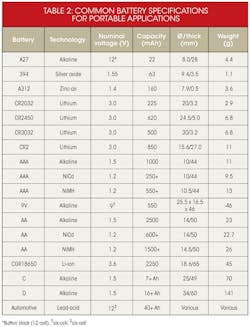
Inherently the FSK transmitters will drain more current because the signal is “always on” during a transmission (because the data is encoded in the frequency of the signal). In contrast, an ASK transmitter turns the PA on and off, so during the “off” cycle the system is not using as much current. The importance of current drain becomes more apparent when compared to the batteries that will provide the current. Each manufacturer provides information on its battery dimensions, capacities, and usage models (Table 2).
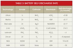
In addition to measuring the current draw of the circuitry, another impact on battery life is the self-discharge rate. For the types of batteries used in ISM applications, this rate is strongly linked to the technology used (Table 3).
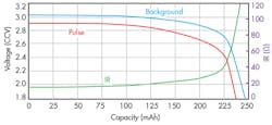
Lithium (Li+) batteries are the most popular for small consumer devices, due to their compact size and long life (low self-discharge). The peak discharge rate and the storage and usage temperature also influence battery selection. Even though these batteries can provide stable voltages for most of their lifetime, each technology suffers from a form of voltage fade caused by a gradual increase of the series resistance within the cell (internal resistance, or IR). This fade is often used to specify the minimum operating voltage of a radio. When lithium batteries reach 90% of their nominal voltage, though, the remaining useful current begins to reach its limit as well.
For example, when a CR2032 battery has been used for 200 mAh, the internal resistance doubles from the nominal value of about 15 Ω to about 30 Ω, while the voltage drops from 3.0 V to 2.8 V (Fig. 2). The knee at 225 mAh shows the battery with an IR of approximately 50 Ω and a supply level at 2.3 V. By that time, the capacity is drained off at 240 mAh, the internal resistance is over 120 Ω, and the voltage has dropped below 1.8 V. The voltage drop, then, is a less critical aspect of the battery life than the complete loss of current capacity.
Range
The predicted range of the system greatly depends on many factors, particularly operating frequency, transmitter output power, antenna efficiencies, and receiver sensitivity. Obstacles, motion, and even atmospheric conditions can greatly influence the operating distance, but these variables are outside the control of a system designer. So, planning for worst-case environments usually limits the design options to TX power, antenna selection, and RX sensitivity.
Transmitter output power can have the biggest impact on the range of the system. Often, higher-than-permitted power is used from the PA to make up for poor antenna efficiencies, due to smaller than quarter-wave geometries, especially in the low bands where antenna efficiencies can be less than 10% (key fob sizes). It is particularly important to stay within any regulatory requirements of the targeted region of operation. More power may be permitted if the duty cycle of the transmitter is varied according to the governing bodies.
When selecting a PA based on output power, remember:
- A higher output power requires higher supply current.
- The higher frequency bands require higher operating current (commonly due to phase-locked loop current).
- Higher output power may impact regulatory limits such as maximum radiated power, occupied bandwidth, and harmonic power.
On the receiver side of the system, the sensitivity is the overwhelming governor of obtainable range. Similar to the transmit side, a receiver that can pick out a signal with 3 dBm less power may be able to compensate for a bad antenna or a poor link environment. When selecting for a receiver’s sensitivity, remember:
- Generally receivers have better sensitivity for ASK modulation.
- Receivers typically exhibit better sensitivity for lower frequencies.
- The data rate has a noticeable impact on sensitivity with much better numbers for low speeds.
Selecting a protocol for your application can be the final step of the system design or the starting point, depending on the application. Protocols govern how the radios will exchange information and include parameters such as telephony (analog audio) requirements, data/bit structure, encoding methods, handshaking exchange processes, and network disciplines for sharing the airwaves.
There are many standard protocols to choose from and just as many proprietary forms of communication. Usually the design parameter that has the greatest impact on the protocol selection is whether a one-way or two-way system is being used. Two-way systems tend to be more complicated, due to a need to negotiate the airwaves and prevent collisions between different radio nodes.
Applications, Tradeoffs, And Guidelines
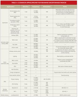
Various applications tend to group into specific communication directions, frequencies, and modulation techniques due to their common requirements or limitations. Table 4 summarizes typical usage models based on the application and provides guidance for frequencies and modulation methods commonly found in each application.
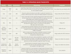
Each application, market, and design will be different, so each will have different priorities. Table 5 summarizes the various tradeoffs encountered by ISM radio system designers and provides suggestions for operating bands and modulation.
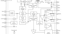
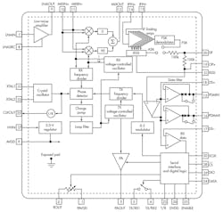
A wide variety of single-chip transmitters, receivers, and transceivers is available from multiple manufacturers (Fig. 3). All necessary circuitry is provided, and only a few external components are needed to make a complete system.
When building up a schematic for transmitters, typically the only other components necessary are a microcontroller or simple encoder interface, an antenna matching network, and some form of power supply. For the receivers, a number of tuned circuits will have to be configured for the frequency of interest and data rate, in addition to the microcontroller or decoder interface and the power-supply system.
Once the schematic is ready, keep in mind that most of the design problems encountered in RF systems can be traced back to a bad PCB layout. Reading up on the most common critical issues to avoid in PCB layout can save some time in the testing and debug phases of system development.
>> Website Resources
.. >> Library: TechXchange
.. .. >> TechXchange: Radio Design 101
