This file type includes high resolution graphics and schematics when applicapable.
As cellular service providers seek to support more subscribers using data-intensive applications like video, small-cell networks are becoming essential for providing the requisite coverage and capacity. As part of their outdoor network plans, service providers are looking at distributed antenna systems (DASs) to create the small cells they need.
DAS technology has been around for more than 20 years. But now, the need to do more with fewer assets is driving innovation in DASs and optical networks. DAS solutions not only address the need for small-cell delivery, they also address efficient small-cell backhaul. Mobile operators are anxious to implement the latest DAS and fiber technologies to create leaner, more cost-effective deployments.
Table Of Contents
• Solutions For Fiber Efficiency
A DAS is a system of managed hubs and remote antennas that distributes a wireless signal to a series of connected indoor or outdoor multi-band, multi-technology radio heads. At the head-end of the DAS, service providers typically locate basestations to provide the cellular signal. A main hub takes that signal, digitizes it, and distributes it to other hubs and radio heads via a high-bandwidth fiber optic network. At the antenna, the radio converts the signals from digital to RF and RF to digital.
Related Articles
- What's The Difference Between A Dipole And A Ground Plane Antenna?
- What's The Difference Between Message Centric And Data Centric Middleware?
- Multi-Antenna Techniques Require Thorough Testing Solutions
By digitizing the signal on the fiber, the DAS can transport the mobile signal at full strength to any remote antenna connected, no matter how far away it is from the main hub and basestation. This is in contrast to older, analog systems that transported RF signals over coaxial cabling and whose performance diminished in proportion to the distance of the remote antenna from the main hub.
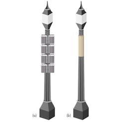
DASs are used in urban canyons, suburbs, airports, stadiums, office buildings, and other venues where service providers need to enhance their coverage or network capacity. By focusing a basestation’s signal on a specific area through remote antennas, the DAS delivers higher capacity and consistent coverage over the area it serves. Some DAS projects extend for miles and support thousands of subscribers. And to keep the mobile network out-of-sight, DAS remote antennas can be housed on lampposts, telephone poles, street cabinets, or other street furniture (Fig. 1).
DASs often are evaluated against other small-cell technologies such as picocells and microcells that providers seek to address a coverage or capacity problem. But picocells and microcells, while cheap and easy to install, typically support only one service provider’s frequency band, so they offer low capacity. In addition, a picocell supports only a couple of dozen simultaneous subscribers, so it serves a relatively small area and limited capacity. Finally, each picocell or microcell requires its own backhaul connection to the network, which multiplies costs. In an area where subscribers demand coverage for all major service providers, a DAS can support multiple frequency bands and service provider services with a single set of antennas and a single backhaul connection.
Solutions For Fiber Efficiency
One of the key challenges in rolling out small-cell architecture is accessing the necessary fiber to make the backhaul connections. Potentially, a service provider would have to build a whole new fiber network to support a DAS or small-cell deployment. But there are several ways in which a DAS makes more efficient use of fiber than picocells or microcells.
First, the DAS requires only one backhaul connection for the entire DAS network. In contrast, each picocell or microcell requires its own backhaul connection. In the case of DAS, the fiber backhaul connection can serve thousands of subscribers, while a picocell or metrocell’s fiber connection would serve only a relative handful of subscribers.
Second, the DAS provides a built-in aggregation point in the network. A modern DAS can do 8:1 aggregation out of the main hub, aggregating up to eight different frequency bands over a single fiber pair. In contrast, a service provider would have to deploy separate picocells or microcells to support each frequency band.
Several other fiber-saving technologies can be used as well. For example, DAS head-ends can aggregate the capacity from two or more basestations so the mobile operator can increase capacity by simply adding another basestation (no additional head-ends, antennas, or radio heads are required). In addition, advanced fiber solutions offer optional fiber-saving technologies:
• All-digital transport: Digital DAS solutions transport RF signals in digital format from the head-end to the radio head or remote antenna unit. This means the signal does not attenuate between the head-end and antenna, and the head-end can simulcast the digital signal to all of the remote antennas in the system.
• Capacity aggregation: Modern DAS solutions can simulcast the capacity from the connected basestation(s) to all of the remote antennas or radio heads in the system. Capacity aggregation saves on basestations and head-end units and simplifies network design and management.
• Fiber-saving technologies: Several fiber-saving technologies can be used to minimize the amount of fiber that needs to be pulled and spliced. The first option is to use coarse wave division multiplexing (CWDM) or dense wave division multiplexing (DWDM) to expand the data-carrying capacity of individual fibers and fiber pairs by multiplexing eight (CWDM) or 80 (DWDM) wavelengths on a single fiber.
Another emerging option is cost-effective 10-Gbit/s transport solutions that slash the amount of fiber needed in a DAS network. A 10-Gbit/s transport can support up to 225 MHz of spectrum over a single fiber pair, which is more than three times the capacity of many baseband transport alternatives. This coupled with CWDM or DWDM offers significant capacity delivery over a single fiber.
A DAS is an efficient means to distribute RF spectrum from a common RF source, where the base transceiver station (BTS) signals are connected to a host, which distributes the BTS’s signal to multiple remote antenna locations via a fiber network.
To avoid having to build out a whole new fiber network for a DAS, service providers can partner with wireline carriers to piggyback DAS traffic on an existing fiber-to-the-x (FTTx) installation. Wireline carriers can participate in this model most easily by offering “a la carte” services to the wireless service provider that provide access to fiber, offer optical efficiencies, or provide leased physical space for the network infrastructure and gear.
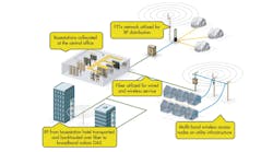
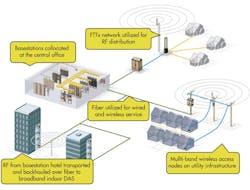
DASs overlay nicely onto FTTx networks (Fig. 2). The fiber in an FTTx network typically originates in a serving office with great access to necessary facilities to host or “hotel” BTS resources. Access to electrical, backhaul, HVAC, and, importantly, fiber to the remote nodes creates an environment where the wireline operator can lease space, eliminating the need for the wireless operator to develop a new site to locate the BTS resources. The wireline operator then has the fiber from this serving office running deep into the network serving its FTTx investment.
By either utilizing spare dark fibers or offering wavelength services from the FTTx plant, the wireline carrier can recognize recurring revenues leasing these fibers to the wireless operators for their use to distribute the BTS capacity to remote DAS nodes. In this scenario the wireline carrier has the opportunity to further monetize its investment while the wireless operator has a cost-effective and time-to-market efficient solution to deliver wireless services.
To overlay a DAS on an FTTx network, the wireline carrier can:
• Monetize spare or dark fibers that may be available as reserved for spares or expansion of the wireline network
• Use optical splitters that link the wireless signal from the basestation to the FTTx network for distribution to the remote units
• Offer wavelength services where dark fibers are not available
• Use a CWDM or DWDM to split out wavelengths for use in the DAS, minimizing fiber usage
• Speed time-to-market by using existing fiber assets to take advantage of zoning approvals already completed
• Utilize space within a central office, basement, enclosure, or hut to house wireless carrier basestations that will provide the signals for the DAS.
• Utilize common backhaul, power, and HVAC to minimize cost and environmental impact
• Minimize time-to-service with easy-to-zone, non-aesthetically disruptive solutions overlaid on the existing infrastructure and real estate
Another of the enduring challenges in matching up a DAS with a mobile basestation has been the need to use RF as the method of interface, which adds complexity and cost to the deployment. But to date, DAS equipment has not been able to use the Common Public Radio Interface (CPRI), which has been defined for basestations. Now, DAS equipment that does use CPRI is emerging, solving several key problems.
CPRI defines the publicly available specification for the key internal interface of radio basestations between the radio equipment control (REC or basestation) and the radio equipment (RE, or radio head). The companies cooperating to define the CPRI specification now include Ericsson, Huawei, NEC, Nokia Siemens Networks, and Alcatel-Lucent. The CPRI specification has gone through several revisions, and today it is at version 5.0.
The idea behind CPRI was to create an open standard for interfacing basestations with radio heads. But in reality, CPRI is neither common nor public, as it is not truly an open standard. Instead, similar to what happened with the Integrated Services Digital Network (ISDN) for public branch exchanges (PBXs), each manufacturer developed its own flavor of CPRI that works only when interfacing its own basestations with its own radio heads.
Since the major basestation manufacturers don’t make DAS equipment, DAS systems supplied by third-party OEMs until now haven’t been able to interface the DAS head-end equipment directly in the digital domain with basestations through CPRI because each BTS manufacturer’s CPRI interface is unique.
Instead, the DAS head-end interfaces with basestations through the RF signal. This has been true since the inception of DAS more than 20 years ago. However, there is a significant power mismatch between basestations and DAS head-ends that must be accommodated for this interface to work. A typical basestation puts out about 40 W, and a DAS head-end takes in roughly 0.25 W. Feeding 40 W into a DAS will destroy the head-end. As a result, the basestation’s power must be severely reduced before it can interface with the DAS.
There are several challenges with reducing basestation power output:
• Complexity: Basestation power is reduced with racks of passive equipment called attenuators. All of this external “plumbing” between the basestation (which can also include splitters, combiners, circulators, etc.) and the DAS adds to the size, complexity, and cost of the deployment.
• Space: Racks of attenuators take up floor space, making a DAS deployment much larger than it needs to be. In many cases, there may not be enough floor space at the intended facility to accommodate the entire deployment, so a separate, off-site facility must be built. This added expense can be a deal-killer for many mobile operators.
• Heat: RF attenuators generate a lot of heat, making it necessary to spend more on air conditioning in DAS deployment areas.
• Cost: The need for attenuators (and the rest of the aforementioned plumbing) and the need to invest manpower resources in designing and deploying all this RF plumbing adds capital and operating expenditures to the overall deployment, worsening the DAS business case for mobile operators.
• Inefficiency: Mobile operators invest in large, hot, power-hungry amplifiers for their basestations, only to have their power substantially reduced in the actual deployment. Amplifiers are one of the biggest cost drivers in a basestation.
Interfacing directly with a basestation via CPRI instead of RF eliminates the need for all this plumbing, saving space, power, and cooling costs in the DAS deployment. All of these elements are critical when evaluating the practical and financial viability of DAS deployment. DAS manufacturers’ ability to use CPRI interfaces versus traditional RF will greatly improve deployment time and the business cases for mobile operators, increasing DASs’ market reach. Obviously, this will require direct cooperation from the basestation manufacturers, as custom CPRI interfaces will need to be developed to work with each major basestation manufacturer.
As we have seen, there are many advantages to be gained by deploying DAS with fiber networks. As mobile operators seek to provide robust and reliable services to their subscribers, DAS and fiber will play key roles in service rollouts.
This file type includes high resolution graphics and schematics when applicapable.


