What You'll Learn:
- What are MIPI interface standards
- Why UniPro is a key MIPI protocol
- What is next from the MIPI Alliance
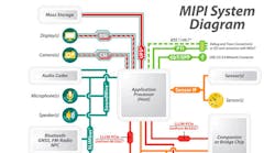
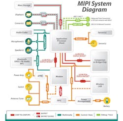
A broad portfolio of interface specifications from the MIPI Alliance enables design engineers to efficiently interconnect essential components in a mobile device, from the modem and antenna to the peripherals and application processor.
Related Articles
- MIPI Physical Layer Transmitter Test Solutions
- The MIPI M-PHY Reduces Power In Mobile Chip-To-Chip Interfaces
- MIPI And PCI Express Join Forces
Most smartphones on the market today employ at least two MIPI specifications. Some products employ MIPI specifications for a full range of internal connections. MIPI specifications have enabled manufacturers to simplify the design process, reduce design costs, create economies of scale that lower price points, and shorten time-to-market for components, features, and services.
Fundamentally, every MIPI specification addresses the industry’s needs for three key characteristics that are essential for any successful mobile design: low power consumption, high-performance operations, and low electromagnetic interference (EMI). MIPI currently has a pair of high-speed physical-layer (PHY) specifications, M-PHY and D-PHY, to support a full range of application requirements in mobile terminals.
Download this article in .PDF format
This file type includes high resolution graphics and schematics when applicable.
The MIPI Alliance makes its specifications available as individual interfaces, enabling companies to adopt those that meet their particular needs. As mobile connectivity increasingly finds its way into other industries—from the PC sector to consumer electronics and machine-to-machine (M2M) communications, among others—external organizations are finding they can use MIPI’s specifications to support these applications as well.
M-PHY: The MIPI “Performance” Interface
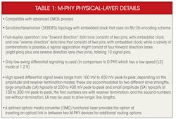
M-PHY provides the fundamental, preferred MIPI high-speed PHY specification for data transmission in a mobile terminal (Table 1). This very versatile specification enables designers to implement a variety of essential high-speed applications in a device while meeting the strict low-power and EMI requirements present in the mobile environment.
M-PHY was released in April 2011. The most current release, v3.0, was published in September 2013. Manufacturers use the specification in smartphone and tablet designs to support high-speed chip-to-chip connections from the application processor to modems from multiple wireless communication standards, storage devices, and emerging high-resolution multimedia elements like cameras for still shots and video streaming.
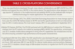
Today, with computing applications from the PC ecosystem moving into the mobile environment, M-PHY also services platforms from the PC ecosystem. The M-PHY is thus a technology bridge allowing convergence between smartphones and PCs (Table 2). With M-PHY, designers can develop across platforms to efficiently address multiple markets and use cases for their products.
M-PHY offers transmission rates across three high-speed ranges, called gears. It gives designers the flexibility to implement their preferred gear to match application requirements. Designers also can use multiple gears to increase data rates and meet the performance requirements of demanding protocols that operate on M-PHY, such as USB 3.0.
Depending on the configuration, M-PHY data rates per lane range from 1.25 to 5.8 Gbits/s. M-PHY also provides dual-frequency capability (“a” and “b”) for each gear to help designers reduce EMI in their systems. A designer can select the preferred operating frequency based on radio interference conditions in the mobile device. M-PHY current data rates per lane include Gear 1 at 1.25 Gbits/s (G1a) and 1.49 Gbits/s (G1b), Gear 2 at 2.5 Gbits/s (G2a) and 2.9 Gbits/s (G2b), and Gear 3 at 5 Gbits/s (G3a) and 5.8 Gbits/s (G3b).
M-PHY is a full-duplex design, allowing physical lanes to operate concurrently in both transmit and receive directions. Lanes can be implemented asymmetrically to serve and benefit camera, modem, and other applications that are highly asymmetric in traffic consumption. Lane asymmetry is a differentiator for M-PHY compared to other PHY protocols.
The most important categories for M-PHY applications include multimedia and chip-to-chip interprocess communications (IPC).
Multimedia interfaces that use M-PHY include MIPI’s Camera Serial Interface-3 (CSI-3) and the JEDEC Solid State Technology Association’s Universal Flash Storage (UFS). Both of these interfaces rely on the MIPI UniPro (Unified Protocol) transport layer, which together with M-PHY forms the UniPort-M interface used in a number of MIPI and non-MIPI specifications.
Chip-to-chip IPC interfaces include MIPI’s UniPort-M interface based on M-PHY and UniPro layers; the PCI-SIG’s M-PCIe interface based on M-PHY and the PCI Express protocol layer; and the USB-IF’s SSIC interface, which is based on M-PHY and the USB3 protocol.
Mobile terminals must operate at very low power to preserve battery life. They also must produce very low EMI to minimize interference between the many radios that can be present in a device, which can include 3G and 4G/LTE mobile broadband technologies, Wi-Fi, Bluetooth, and Global Navigation Satellite Systems (GNSS), including GPS and other satellite constellations.
M-PHY can achieve low-power consumption for a wide range of data rates. It uses a standard differential pair for data transmission, but achieves low power consumption from low-voltage swing operation. The differential voltages also minimize noise, enabling the device’s very sensitive receivers to operate at high performance levels. M-PHY improves low-power performance as well by offering advanced power management techniques such as low latency transitions between power states.
Low EMI is enabled via the low-voltage swing operation, the use of dual-frequency operation to avoid interference to radio receivers used by other critical applications in the device, and slew rate control.
D-PHY: A Practical PHY For Typical Camera And Display Applications
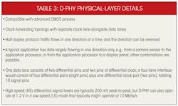
D-PHY was developed primarily to support camera and display interconnections in mobile devices, and it has become the industry’s primary high-speed PHY solution for these applications in smartphones today (Table 3). It is typically used in conjunction with MIPI’s Camera Serial Interface-2 (CSI-2) and MIPI’s Display Interface (DSI) protocol specifications. It meets the demanding requirements of low power, low noise generation, and high noise immunity that mobile phone designs demand.
The standard has been available since November 2005. The most current release, v1.1, was published in November 2011. One of the primary differences between D-PHY and M-PHY is data speed. D-PHY delivers data at up to 1.5 Gbits/s per lane, and typically four or eight lanes are used. M-PHY, for comparison, offers three speed grades, or gears, with the fastest configuration (Gear 3b) delivering 5.8 Gbits/s per lane. D-PHY also uses a conventional clock-forwarding technology, which is suitable for most cameras and displays in the market and simplifies implementation for these applications. M-PHY, on the other hand, uses an embedded clock structure to support applications that demand such capabilities.
D-PHY is a flexible specification that gives designers a lot of choice when selecting specifications to meet their specific product requirements. Designers who are building devices to serve prevalent camera and design trends in the ecosystem will find that D-PHY is the preferred solution that meets most of the market’s needs. The comparative simplicity of D-PHY compared to M-PHY can also reduce the complexities and costs of implementation. If designers are interconnecting higher-performance cameras and planning to use the CSI-3 interface, however, they will need to employ the M-PHY specification at the PHY.
UniPro: A Key MIPI Protocol
MIPI’s UniPro (Unified Protocol) is a transport layer. When implemented on top of M-PHY, it forms the UniPort-M interface that manufacturers can use to support a wide range of component types in a mobile device. UniPort-M can be used with MIPI or non-MIPI interfaces. It was developed as a standalone interface for IPC and similar applications, as well as a building block for multimedia interfaces. Its versatility simplifies the interconnection of peripherals and reduces time-to-market and design costs. Target devices for UniPro/UniPort-M applications include smartphones, tablets, digital cameras, and multimedia devices.
UniPro has been available since February 2007. Its most current release, v1.6, was published in September 2013. MIPI’s next-generation Camera Serial Interface (CSI-3) uses the UniPort-M interface to connect sophisticated cameras with the application processor. External to MIPI, the JEDEC organization uses UniPort-M to provide the basis for its Universal Flash Storage (UFS) specification.
One of UniPro’s key technical characteristics is its ability to support various traffic classes. This feature can be used, for example, to deliver traffic across the interface in real time or non-real time. UniPro can also support networking of various connected devices, enabling designers to define the type of data traffic used for individual components.
Camera Interface Specifications: CSI-2 And CSI-3
The MIPI Alliance’s Camera Specifications define the interface between the camera or multiple cameras and the application processor or image signal processor (ISP) in a mobile device. CSI offers a choice of two interface protocols: CSI-2 and CSI-3. Manufacturers can select the interface based on prevailing marketplace trends that will impact their design, the performance characteristics their product requires, or the complexity and costs of the implementation.
CSI-2, available since 2005, has achieved widespread adoption and is used to interconnect cameras and application processors in virtually every smartphone built today. It is the most logical choice for any design targeting the smartphone market, offering a robust, scalable, low-power, high-speed, cost-effective interface that supports a wide range of imaging solutions for mobile devices. CSI-2 uses the MIPI D-PHY specification for the data transport PHY and CSI-2’s Camera Control Interface (CCI), compatible with I2C, as the control channel. Most smartphones today operate the CSI-2/D-PHY interface on four or eight data lanes, depending on the product’s performance requirements.
CSI-3, MIPI’s next-generation interface, is a preferred option for designers who are working with new, higher-performance camera technologies and need a greater total data rate than can be delivered with CSI-2. The CSI-3 interface, available since 2012, is based on the UniPort-M interface. It can service high-resolution, high-megapixel sensors, facilitate high frame rates needed for teleconferencing and camcorder functionality, support applications such as stereo image capture, and, with a high-speed, bi-directional capability, respond quickly to demanding camera control requirements.
Display Serial Interface (DSI): Ubiquitous And Versatile
MIPI’s Display Serial Interface (DSI) specification defines the interface between the processor and the display or multiple displays. Available since 2006, it has achieved widespread use and is the dominant display interface used in smartphones today. DSI uses the MIPI D-PHY for both data transport and control. It makes D-PHY’s half-duplex feature available for those devices communicating bi-directionally on the same physical wires.
Most smartphones today use the DSI/D-PHY across four or eight lanes. It can support brilliant, realistic color rendering for the most demanding high-definition imagery and video scenes. It also can support use and even synchronization of multiple displays over the same interface link.
MIPI continues to advance DSI and has collaborated with the Video Electronics Standards Association (VESA) to develop a data compression and transport scheme that will reduce the required data rate for high-resolution mobile display applications, reduce the power consumption of these systems, and lower the costs for implementing them. As a result, MIPI has developed an update to DSI that employs VESA’s Display Stream Compression Standard as an optional feature. The respective specifications have been completed and are in the final phases of approval by each organization.
Battery Interface: An Industry-First Solution
The Battery Interface (BIF) specification provides a standardized approach for connecting the power management chip in a phone to the battery. BIF specification v1.0 was released in 2012 as the first complete battery communication interface specification for mobile devices. Addressing years of fracture in the market, it replaces a number of proprietary interfaces used while improving speed and control capabilities to support smarter power management.
Designers can use this single interface in a wide range of mobile devices. Its availability promotes uniformity in the market, helps reduce design and implementation costs, and helps streamline testing. MIPI developed BIF specifically to minimize battery complexity while ensuring safe and efficient charging control under all operating conditions. Designers will find that it is as straightforward and convenient to use as I2C.
Radio Frequency Front End (RFFE): A Single Unifying Specification
The Radio Frequency Front End (RFFE) interface provides a standard control interface from the RF transceiver/baseband to numerous mobile front-end devices including power amplifiers, low-noise amplifiers, filters, switches, power management modules, antenna tuners, and sensors. It helps reduce the cost of these components. It also helps improve the radio performance in smartphones that use increasingly complex, multi-radio systems. Its use in antenna tuning is expected to become particularly important for LTE-based products that must operate in multiple frequency bands worldwide.
Released in 2010, RFFE is now available as v1.10. It replaces a variety of proprietary and standard interfaces such as SPI and I2C that have been used in the market to date. RFFE is a compact, two-wire interface, using a clock signal and a bi-directional data signal and operating at a maximum frequency of 26 MHz. It employs a point-to-multipoint structure to enable control of multiple RF front-end devices. It also can support up to 15 slave devices on a single RFFE bus.
RFFE offers a time-accurate triggering mechanism to facilitate control of timing-critical functions in multiple slave devices. The specification defines a variety of command sequences that can be used to determine the amount of data that can be transferred on the bus. Additionally, the RFFE interface employs slew-rate controls to help mitigate emissions at sensitive radio receivers.
eTrak: A New Envelope Tracking Specification
MIPI’s Analog Reference Interface for Envelope Tracking (eTrak) specification has been defined to support the deployment of envelope tracking (ET), which is gaining strong momentum in the mobile industry. ET is a technique for reducing power consumption in the RF power amplifier to improve the overall efficiency of the radio transmitter, which is a significant source of power consumption in a mobile device. It is particularly needed when a mobile device is transmitting at a high data rate via 3G and advanced 4G cellular technologies, and it will become a standard feature with the continuing development of LTE in mobile devices.
The eTrak specification provides a standard control methodology for ET in mobile device RF power amplifiers, yielding large improvements in power amplifier efficiency. The specification provides a point-to-point interface that connects the baseband or radio-frequency IC to the ET power supply (ETPS) and facilitates interoperability between chipsets and the ETPS to support wide deployment of ET technologies. This high-speed, uni-directional analog differential interface offers sufficient bandwidth to support LTE 20-MHz operation. The interface ensures extremely low noise performance to avoid interference with the cellular radio receiver.
MIPI’s eTrak specification v1.0 was released in August 2013. An application note to support the specification will be released in early 2014, followed by the publication of a conformance test suite.
Looking Ahead
The MIPI Alliance continues to advance device interfaces to meet the mobile market’s demands for additional end-use applications and capabilities. As additional industries embrace the combination of high performance, low power consumption, and low EMI characteristics that MIPI specifications provide, MIPI will expand beyond its traditional mobile designs and into new types of devices and industries.
These new sectors will also need the interoperability benefits that MIPI interfaces offer to create economies of scale and drive mass market adoption of their new technologies. MIPI specifications are already used in many solutions for vertical markets, such as automotive and medical applications. During the next 10 years, the MIPI Alliance expects its technologies could have roles to play in wearable devices, augmented reality, M2M communications, and emerging products in the Internet of Things. There could also be a need for MIPI specifications targeting the interconnection of optical elements in mobile and other high-performance devices.
