Modern high-speed RS-485 data links are pushing the envelope to the absolute breaking point with regards to data rate versus cable length. Applications include position encoders, traffic monitoring, seismic networks, and GPS transceivers.
This file type includes high resolution graphics and schematics when applicable.
Data rates from as low as 8 Mbits/s up to 20 Mbits/s are driven across distances of 200 to 1000 feet (70 to 300 m). The designs of such data links are rather complex because additional efforts must be implemented to compensate for increased propagation delays of cable and transceivers, as well as frequency-dependent cable losses.
Data Rate Versus Cable Length
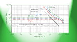
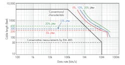
Figure 1 shows the conventional cable length versus data rate characteristic. At about 4000 feet, the voltage divider action between the cable resistance of a 24 AWG twisted-pair cable and the termination resistance matching the characteristic line impedance reduces the signal strength by half (6-dB attenuation). This drop serves as a reference for the maximum cable length, which is why many long distance networks mainly transmit at 10 to 20 kbits/s, rarely at 100 kbits/s.
At higher speeds the R-L-C line characteristics kick in, limiting the maximum cable distance with increasing data rates for conventional transceivers. At even higher rates the transceiver characteristics solely determine the signal quality. The range between 1 and 10 Mbits/s is where many modern applications aim for longer cable runs.
Using conventional high-speed transceivers still produces enormous jitter content due to the transmission medium’s propagation delay, insertion loss, high-frequency rolloff, data pattern-dependent inter-symbol interference (ISI), and delay skews in multi-pair, screened, and unshielded twisted-pair cable (UTP).
Synchronous Data Link
Considering a data link consisting of a signal source (transmitter), the transmission medium (cable and connectors), and the signal sink (receiver), each section has its own propagation delay and delay skew that contributes to the total prop-delay and skew of the link.
Synchronous interfaces consist of two data links, one for the synchronizing clock and one for the actual data channel (Fig. 2). To ensure proper data communication, the signal timing between both channels must be accurate to prevent bit errors at the receiving end. Thus, the overall propagation delay is less important than the delay skew between the two channels.
The terms of cable propagation delay and delay skew are easily understood. Propagation delay exists for all types of transmission media. This delay is the time that passes between when a signal enters a cable channel and then exits at the other end. The delay value for twisted-pair cabling is a function of the signal velocity through the cable, the cable length, and the signal frequency.
The velocity varies with the dielectric materials used in the cable and is a percentage of the speed of light. Most category 5 (CAT-5) cables have velocities of 65% to 70%, whereas dedicated RS-485 cables, such as Belden 3105A (single-pair) and 3109A (multi-pair) cables, have velocities of up to 78%.
Lower velocities contribute to higher delays for a given cable length, just as an increase in cable length causes a proportional increase in prop-delay. Like most other transmission parameters, prop-delays are frequency-dependent.
Multiple signal pairs in the same cable sheath commonly have different prop-delays. Known as delay skew, this difference is affected by the differences in twist rates from pair to pair to minimize crosstalk between signal pairs.
To ensure proper signal transmission, local-area network (LAN) standards specify prop-delay and delay skew in nanoseconds per 100-m cable lengths. For CAT-5 and CAT-5e cable, the maximum nominal propagation delay and delay skew are 550 ns/100m and 45 ns/100m, respectively. Even for dedicated EIA-485 cables with much shorter prop-delays, the delay skew can still reach 15 ns/100 m.
Depending on the signal data rate, the cable length and the transceiver timing performance, the skew between clock and data channel must be eliminated. Typically, this is accomplished through propagation delay compensation at the receiving end. Here, FPGAs include hardware-coded algorithms that measure the time difference between the first arriving signal (either clock or data) and the later arriving one. For this purpose, the implemented logic often uses a sampling clock that is eight times the transmission clock, which in turn is twice the actual data rate.
When considering sending a 5-Mbit/s data stream across a data link, the transmission clock is 10 Mbits/s or 5 MHz, while the oversampling clock in the FPGA is 40 MHz. To keep the delay compensation limited to one transmission clock cycle and, thus, relatively simple, the combination of signaling rate and transceiver and cable performance is important. Hence, at significantly higher data rates the use of high-quality cable with minimum skew is often advised.
Note that a discussion delay skew between transceiver components, also known as part-to-part skew, is mainly important for short data links as there is a chance to avoid delay compensation entirely. For long cable runs, however, the cable’s delay skew dominates as it is several times longer than transceiver part-to-part skew.
Asynchronous Data Link
Other factors of high-speed transmission across long distances are the frequency-dependent losses of the cable, predominantly occurring at high frequencies. Consequently, a clock signal at the driver output, appearing as a crisp square wave at the driver output, turns into an almost sinusoidal shape at the receiver input.
Similarly, this holds true for the data signal, whose bit-dependent pattern can be clearly distinguished at the driver output. Heavy capacitive loading through the cable, though, drastically rounds the signal edges and causes inter-symbol interferences (ISI), resulting in large signal jitter. Here, the charging and discharging of the cable capacitance can cause the loss of entire bits when the bit pattern changes from a long sequence of high bits to a short low bit and vice versa.
To prevent unequal charges and discharges, encode the data signal into a clock-like data stream. A commonly applied coding scheme in RS-485 applications is Manchester coding.
The simplest Manchester encoder design is an XOR-gate connected to a serial peripheral interface (SPI) port. Low-to-high and high-to-low transitions at the encoder output represent high and low bits on the data line, while long bit streams of equal polarity are converted into clock cycles. The encoded signal is applied to the driver input and transmitted across the data link. Decoding happens at the receiver output. While the decoder logic is a little more complex, it is easily implemented into an FPGA (Fig. 3).
Signal integrity is further improved with transceivers providing receiver equalization, which amplifies the high-frequency components of the receiver input and signal. Here, an active high-pass filter is implemented between the cable end and the input comparator.
While this approach is straightforward, noise-sensitivity considerations make the optimization of the internal filter response to certain applications necessary. As such, lower filter orders are applied for approximating the cable attenuation in the lower megahertz range, while higher filter orders provide equal accuracies in the tens of megahertz.
Receiver equalization reigns provide the benefits of avoiding high-frequency emissions, making it the preferred solution in EMI-sensitive (electromagnetic interference) applications, while keeping the increased power consumption caused by the high-pass filter negligible.
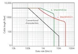
Figure 4 compares the signaling-rate versus line-length characteristics of transceivers with receiver equalization with the characteristic of a conventional EIA-485 transceiver. Device a can transmit at 10 Mbits/s across 250 m of cable. By pushing the limits to allow for some minor jitter, even 300 m can be achieved easily. Device b, however, can drive data at a lower rate of 5 Mbits/s over more than 500 m, almost twice that distance.
Therefore, combining Manchester coding with receiver equalization yields a cost-saving, single-channel, asynchronous data link. Unlike its synchronous counterpart, it neither requires a separate clock channel nor specific cable quality to ensure reliable data transmission.
Conclusion
To get high-speed data reliably across long cable lengths, ultra-precise timing requirements of high-quality cables and cost-intensive precision transceivers are not needed. Instead, a solid proven coding scheme combined with low-EMI receiver-equalized transceivers provides a reliable data link at low cost.
To support high-speed data links with large ground potential differences, Texas Instruments’ transceivers with integrated equalization, such as the SN65HVD23 and SN65HVD24, provide a wide common-mode voltage range from –20 V to +25 V.
References
• EnDat 2.2 – Bidirectional Interface for Position Encoders, HEIDENHAIN
• Manchester Coding Basics, Atmel
• Clark Kinnaird, Use Receiver Equalization to extend RS-485 Data Communications, Application Report (SLLA169), Texas Instruments, August 2004
• Here’s more information from TI about RS-485
• Download these datasheets: SN65HVD23 and SN65HVD24
Thomas Kugelstadt is a senior systems engineer with Texas Instruments. He is responsible for defining new, high-performance analog products and developing complete system solutions that detect and condition low-level analog signals in industrial systems. He is a graduate engineer from the Frankfurt University of Applied Science. He can be reached at t[email protected].


