This file type includes high resolution graphics and schematics when applicable.
Practically every electronic product made today uses one or more serial data interfaces. A serial interface is the fastest and easiest way to get data into or out of a device. With so many different types of devices populating an enormous range of applications, it should come as no surprise that literally dozens of different interfaces are available for every occasion. USB, HDMI, and RS-232 are perhaps the most common interfaces, but many others also occupy this space.
Rationale for Serial I/O
Digital data flows into or out of a circuit or device using two basic methods. The first way is via parallel data interfaces, which transfer multiple bits over parallel data paths. Parallel interfaces require one path, printed-circuit-board (PCB) trace or wire per bit plus a ground. If using balanced differential lines, two paths are required per bit. While this is the fastest way to transfer data, it’s expensive and hardware-intensive because a driver and receiver are needed for each path. And cables for long distances become large and expensive.
The primary limitation of a parallel interface is speed over distance. As data-transfer rates accelerate, the path characteristics dictate an upper limit. Parallel PCB traces or wires in a cable act as filters and transmission lines. Path inductance, capacitance, and resistance introduce attenuation and rounding, thereby limiting the data rate. Furthermore, crosstalk between lines creates mutual noise, and different path lengths introduce bit skew that may affect timing at higher speeds. On top of that, parallel buses generate a significant amount of electromagnetic interference (EMI). All of this reduces the data-transfer range.
Such limitations not only restrict range, but data rate as well. The upper limits depend on specific cases, but the upper data rate is generally in the hundreds of megabits per second over no more than about several feet. That’s why parallel transmissions are usually limited to interconnections between chips on PCBs or over short differential ribbon cables between PCBs or chassis.
Serial data interfaces, obviously the second digital-data-flow method, eliminate or at least minimize this problem. While data transfers are theoretically slower because of the bit-by-bit transfer, today’s data rates range from a few bits per second to 100 Gb/s over long distances.
Serial connections require only a single path, either unbalanced or differential. Data can travel over PCB traces, single wires, twisted pair, coax cable, or fiber-optical cable. Range can be inches to hundreds of meters, or even more. Special line drivers and receivers with equalization deal with the various path distortions. In summary, serial interfaces make it possible to go faster over longer distances with less hardware at lower cost.
One other note: Wireless interfaces are also serial—with only a single free-space path, serial transfer is the only practical method. The most popular short-range wireless interfaces are included in this article.
Categorizing Serial Interfaces
Typically, the two best ways to characterize serial interfaces is by speed and application. This article, however, categorizes interfaces as wired baseband, wired broadband, and wireless. Data provided includes speed, range, media, application, and standard designations. Applications targeted by these interfaces include automotive, consumer, industrial, and PCB interconnects and backplanes. Wireless interfaces are treated separately.
Wired-Baseband Interfaces
Interfaces discussed in this article are grouped by application. Maximum data rates and ranges are provided; data rate depends on range or medium length. Due to space limitations, only the most popular interfaces are listed.
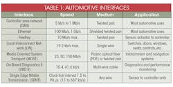
• Automotive interfaces: With so much electronic equipment in cars and trucks, it was a natural evolution to connect things with buses or interfaces. Table 1 shows the most common interfaces used today.
• Consumer/video interfaces: Everyone uses these interfaces almost every day (Table 2). They’re mainly used for video connectivity or PC peripheral connections. The best example is the USB interface, which is by far the most widely used interface in the world (except for, perhaps, the RS-232 interface).
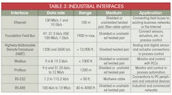
• Industrial interfaces: Factories, plants, process control, automation centers, and other manufacturing facilities all take advantage of industrial interfaces. They connect computers to one another and to a huge variety of machines, robots, sensors, actuators, and other devices such as the widely deployed programmable logic controller (PLC). Some industrial interfaces define only the basic physical layer, while others define specific networking configurations and protocols. Several of these interfaces are referred to a fieldbuses.
The old and reliable RS-232 and RS-485 interfaces still dominate in the industrial sector, but Ethernet has made massive progress in this space due to widespread network connectivity and the subsequent need for higher data rates. Table 3 summarizes the most widely used interfaces in industry, but a number of special interfaces are in play, too.
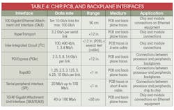
• PCB/backplane interfaces: These interfaces are designed to connect chip to chip or PCB to PCB (Table 4). The faster interfaces are used on backplanes in routers, switches, and other high-speed equipment. I2C and SPI interfaces dominate the chip-to-chip and PCB interconnections. PCI Express (PCIe) is the most widely used fast interface, but there’s competition from HyperTransport and RapidIO. The faster interfaces all use two or more parallel serial links to produce higher throughput.
Wired-Broadband Interfaces
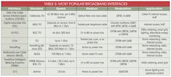
Broadband interfaces use modulation to transmit data—serial baseband data bits modulate a carrier or carriers, which are put on a cable. This is done primarily because data can be transmitted faster over longer distances. The downside, of course, is the greater complexity and cost, since both ends of a link require modulation and demodulation. The connecting device is a modem. Table 5 runs down the most widely used broadband interfaces and their main characteristics.
Wireless Interfaces
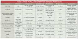
Various wireless interfaces have emerged over the years for specific applications, with a range of success in terms of popularity. Some are used as a cable eliminator, while others just simplify remote connections without the expense of laying cable. Most of these interfaces are designed to cover short ranges, from a few inches up to about 100 meters. Table 6 summarizes the most prominent of this group.
All of these interfaces use the unlicensed frequency spectrum specified in the FCC rules and regulations Parts 15 and 18. Several interfaces are based on the IEEE 802.15.4 standard, including ISA100, WirelessHART, and ZigBee. Applications are across-the-board, from industrial monitoring and control, home networking, and the Internet of Things (IoT) to consumer, smart-grid and utility metering, and general networking.
Testing Serial Interfaces
Before testing any serial interface, you should be aware of the particular standard’s details. It’s best to acquire the documentation from the standards organization. Such documentation spells out the specifications and, in many cases, recommended testing procedures.
The key testing requirements are usually data speed and bit error rate (BER). BER, typically used in high-speed interface testing, is simply the percentage of bit errors per quantity of bits transmitted. BER values range from roughly 10-5 to 10-15, depending on the interface.
Some high-speed interfaces also require eye-pattern testing and jitter measurements. Certain complex interfaces may also need protocol analysis equipment or software.
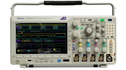
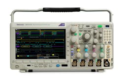
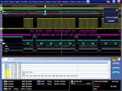
When it comes time to perform the tests, the instrument of choice is a digital oscilloscope with the appropriate software. Most scope manufacturers offer special testing software for the popular serial interfaces. It’s a superior investment, as it greatly speeds up and simplifies testing. Manufacturers such as Keysight Technologies, National Instruments, Rhode & Schwarz, Tektronix, and Teledyne Lecroy offer appropriate equipment and software. In one example, a modern oscilloscope delivers the waveforms and code for an I2C interface (Fig. 1). Figure 2 shows the display for an SPI interface.
Footnote: This article is abstracted from the new book Handbook of Serial Communication Interfaces, A comprehensive compendium of serial digital input/output (I/O) standards to be published by Newnes/Elsevier in the fourth quarter of 2015.
