The Fundamentals Of Thread Visualization For Test Case Understanding And Debug
This article is part of the TechXchange: Addressing Chip Verification Challenges
If there’s one mantra that applies to the development of today’s complicated system-on-chip (SoC) designs, it’s “automate whenever possible.” The design side of the development process took a huge leap forward with the commercial introduction of logic synthesis in the late 1980s. As synthesis became better and even more automated, an individual designer evolved from connecting a few thousand gates by hand to generating hundreds of thousands or even millions of them. Improved reuse of existing blocks also has contributed to the much higher productivity of today’s design engineers.
Related Articles
- The Verification Flow Can Enable Horizontal Reuse
- Remove The Processor Dilemma From Constrained-Random Verification
- One Verification Model To Drive Them All
On the verification side, a similar effect occurred in the mid-1990s with the advent of constrained-random testbenches. Previously, verification engineers read the design specification, iterated all the features in the design, created a test plan listing the tests they planned to write to verify the features, developed a testbench, and then hand-wrote the tests to run in the testbench. Handwritten “directed” tests might have been as simple as ones and zeros, although more sophisticated verification teams used scripting languages and provided some randomization of data values.
This file type includes high resolution graphics and schematics when applicable.
Constrained-random testbenches changed all that by automating test creation. The verification team spent its time creating a testbench that included rules (constraints) on allowable inputs to the design. This enabled automatic generation of many tests conforming to the rules. Since there was no longer a direct correlation between a test and features it verified, verification engineers included in the testbench functional coverage structures related to the design features. Once all of this coverage was hit by the automated tests, verification was deemed complete.
A third revolution is overdue: automation of the C tests that run on the SoC’s embedded processors. Today, most SoC teams devote a group of 10 to 20 verification engineers to handwrite tests for simulation. A typical test suite consists of a few thousand such tests. Once the SoC returns from the foundry, most teams have a similar sized group of validation engineers who handwrite bring-up diagnostics to run on the chip in the lab. There is rarely any overlap between these two teams or the tests that they write. Automating handwritten tests both increases team productivity and fosters reuse throughout the SoC project.
Motivation
The first question one might ask is why handwritten tests are needed at all. Why don’t constrained-random testbenches suffice? The answer lies in the embedded processors that, by definition, are in the SoC. The constrained-random approach, powerful though it is, treats the design as a black box and tries to verify all functionality purely by driving the design’s inputs. Driving deep design behavior purely from the inputs is challenging enough for a large and complex design of any kind. But ignoring the embedded processors exacerbates the situation.
The power of the SoC lies in its processors. When the chip is out in the real world doing whatever it was designed to do, the processors are in charge. It’s just common sense that the verification effort should leverage the embedded processors. Unfortunately, neither the Universal Verification Methodology (UVM) standard nor any other popular constrained-random approach makes any provision for code running on the processors. In fact, they are often removed from the design and replaced by virtual inputs and outputs in UVM testbenches.
As noted earlier, many SoC verification teams have recognized the limits of constrained-random testbenches and have built teams to handwrite C tests to run on the processors in simulation. In some cases, these tests run in acceleration and emulation as well. However, these tests are quite limited in how they exercise the SoC design. Humans are not good at thinking in parallel, so it is rare for handwritten tests to run in a coordinated fashion on multiple processors. The result is that many important aspects of SoC behavior, including concurrency and coherency, are minimally verified.
The second question is why the SoC bring-up team handwrites diagnostics. Since the team’s goal is complete hardware-software co-verification with the operating system and applications all running on the chip, why not just run that code? The reality is that chips rarely arrive from the foundry ready to boot an operating system on day one. Lingering hardware bugs, the bring-up environment, and immature software all cause problems. The bring-up team handwrites diagnostics that incrementally validate SoC functionality. These are stepping stones toward booting the operating system and running applications.
Automation
Clearly, the SoC project will make much more efficient use of resources if handwritten C tests can be generated automatically. The technology now exists to do precisely this, and commercial solutions are available. The generated C test cases can exercise far more of the SoC’s functionality than handwritten tests could ever do. Multi-threaded, multi-processor test cases can exercise all parallel paths within the design to verify concurrency, move data among memories to stress coherency algorithms, and even coordinate with the testbench when data should be sent to the chip’s inputs or read from its outputs.
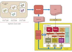
The enabling technology is a graph-based scenario model that captures intended design behavior and the SoC’s verification space while defining a system-level coverage model (Fig. 1). Scenario models are created by design or verification engineers as a natural part of SoC development since they resemble traditional chip data-flow diagrams. These models provide a generator with everything it needs to produce high-quality C test cases that stress every aspect of the design. Scenario models are hierarchical, so any developed at the block level can be reused entirely as part of the full-SoC model.
Thus, automation produces more and better test cases in much less time and with much less effort than traditional methods. SoC teams who have adopted this approach typically require only 20% of the team who used to handwrite tests, with the remaining 80% re-deployed much more productively on revenue-generating software such as applications. Similar savings occur in the bring-up team, since the same scenario model can generate test cases for silicon validation. In fact, one model can generate test cases for virtual platforms, register transfer level (RTL) simulation, simulation acceleration, in-circuit emulation (ICE), FPGA prototypes, or an actual chip in the lab.
One might ask a third question: how in the world is it possible to debug an automatically generated multi-threaded, multi-processor test case? If it uncovers a lurking design bug, the verification team has to understand what the test case is doing to track down the source of the bug. A test case failure might instead be due to a mistake in the scenario model, so it must be possible to correlate the test case back to the graph where the design intent was captured. A unique visualization approach for the generated test cases provides the answer.
Debug
The test cases exercise realistic use cases, called application scenarios, for the design. In the case of a digital camera SoC, one such use case might be capturing an image from the camera charge-coupled device (CCD) array, converting it to JPEG format in a photo processor, and saving the resulting compressed image on an SD card. In the case of a set-top box SoC, a use case might involve tuning into a particular cable channel or Internet site and receiving an MPEG-encoded stream and converting it to video. From there, it’s a matter of buffering several seconds of video on a disk to prevent interruptions when traffic is high and routing the video to the display.
Each test case consists of multiple applications, each built from a series of application scenarios. Each application scenario, in turn, is built from driver scenarios for the individual blocks in the chip, such as the imaging array, photo processor, SD card interface, cable tuner, video processor, disk interface, or display controller. The ability of the test cases to stress the SoC comes from interleaving the applications across multiple threads and multiple processors. The tool will run as many applications in parallel as can be supported by the inherent concurrency of the design.
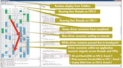
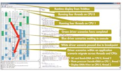
Figure 2 is an example display showing the threads overlaid with the executing applications. The SoC has two embedded processors, and the verification engineer requested that the test case create four threads on each processor. The solid colored lines show how the driver scenarios are interconnected to form application scenarios. This is an actual screenshot from test cases running in RTL simulation of a digital camera SoC. The highlighted scenario shows a JPEG-encoded image being read from an SD card, converted back into a raw bitmap image, and displayed on the camera screen.
This same display is available from test cases running on any platform, including actual silicon in the lab. A display of the threads and scenarios is absolutely essential for the verification and validation engineers to understand what the test case is doing and to debug when it fails. Since the test case is written in C code, the engineer also has available the usual integrated development environment (IDE) and debug features, such as breakpoints, used for handwritten tests and production software. Thus, the complex automatically generated test cases can be analyzed and debugged in a familiar environment.
Conclusion
The automation of design via logic synthesis changed chip development profoundly. The increasing adoption of high-level synthesis from more abstract models is changing it even further. On the verification side, constrained-random testbenches eliminated much of the manual work. The next step in this evolution is the automation of C test cases for embedded processors. Leading-edge SoC development teams have already adopted this approach and more are signing up every day. Soon it will be as unimaginable to handwrite C simulation tests and diagnostics as it is to handwrite directed tests for the testbench or manually connect gates in a schematic diagram.
Adnan Hamid is cofounder and CEO of Breker Verification Systems. Prior to starting Breker in 2003, he worked at AMD as department manager of the System Logic Division. Previously, he served as a member of the consulting staff at AMD and Cadence Design Systems. He graduated from Princeton University with bachelor of science degrees in electrical engineering and computer science and holds an MBA from the McCombs School of Business at the University of Texas.


