What you’ll learn:
- Silicon Valley has several highly toxic Superfund sites from its legacy tech industry.
- Engineers didn’t draft their own schematics in the old days, with temporary workers pollinating the Valley’s tech industry with undocumented schematic-drawing practices.
- Six time-honored SPICE schematic drafting conventions are discussed, with a chance to settle a controversial seventh one with our reader poll.
A schematic is ideally drafted in such a lucid manner that its operation leaps off the page for another electronic engineer. Drafting circuits properly makes design less error-prone, an important focus for any responsible design effort. My own drafting style has evolved over the years. My goal is to document the methods I use, which have been empirically found to allow me to handle larger circuits without errors.
Every style recommended here is based on functionality, but it's beneficial to know a bit of the past. As neither the transistor nor the integrated circuit were invented in Silicon Valley (though the vacuum tube was), most historians see Silicon Valley's origins in instrumentation companies like Hewlett-Packard (founded 1939) and not semiconductor manufacturers like Fairchild (founded 1957).
Silicon Valley was filled with instrumentation companies doing PCB level design. So much so, that the groundwater became dangerous.
What’s that Drawing Fur?
Up until the mid to late 1980s, electronics engineers didn’t draft circuits, as their time was too valuable. Instead, specialized trades would draft circuits under an engineer's auspices. Circuits would be drafted with heavy lead pencils on special translucent paper used to subsequently make blueline prints (“blueprints”) with an ammonia-based process.
This predated the ubiquity of laser-printing copies of circuits for distribution and archives. I actually preferred the European practice at that same time—India ink on true animal-based vellum—since a scalpel could cleanly scrape off India ink without damaging the vellum, allowing for unlimited edits. The American paper-based "vellum" could only be erased a limited number of times before the entire circuit had to be redrafted anew.
Creating Silicon Valley Buzz
Anyway, the drafting trade people were typically temp workers. These worker bees traveled from company to company, cross-pollinating them with these undocumented conventions for schematics. This situation led to drawing practices that became fairly uniform in Silicon Valley.
The following drafting conventions have survived to this day, thanks to the prolific consistency of the drafting techs:
1. The reference designator is drawn above the component value, with both to the right of the symbol. Unless the symbol is drawn horizontally. Then the reference designator goes above the symbol and the component value below the symbol. If that’s followed, two things happen. First, it can be quickly ascertained which reference designators and values go with which components, making the schematic much faster to read. And secondly, personal knowledge is demonstrated of how schematics are supposed to be drawn. The consequences of not following such conventions risked that a senior engineer, who actually did work at one of these early prestigious instrumentation companies, would immediately recognize that the drafter never actually released a design to a document control department in their life.
2. Ground on a circuit board is a triangle, not three lines. Three lines is earth ground. If you use it to mean circuit board common, senior engineers might snicker and ask if you took your circuit outside and connected to that rod stuck in the dirt.
3. Signal flow should be from left to right and current should flow from top to bottom. Follow this as much as possible.
Around 1985, CAD tools came into widespread use, coincident with the emergence of workstations, such as those from Sun, and the personal computer. By 1990, the temp worker bees became extinct because engineers now drafted their own schematics. The change of medium from blueprints to laser-printed CAD drawings allowed drafting style to evolve in the interest of being able to humanly handle larger schematics in a less error-prone manner.
Cross Your Tees—and Dot Them
The following conventions aren’t historically based, rather they’re purely functionally based. The goal is to be concise so it's easier to handle larger schematics.
4. Use ground symbols and not return paths. This dramatically reduces the number of lines on a schematic, making it much easier to read. It also reflects the fact that the CAD tools do a very good copper pour these days, so the return path of least inductance is found automatically.
5. A properly implemented CAD tool will scale junction dots differently than either fonts or graphic objects in the interest of being certain that they’re always visible no matter the scale on the screen or paper. This means that it’s incorrect to stagger wire tees in a misplaced attempt to make it clearer where connections are located. The problem with a staggered cross is that it obfuscates the symmetry of common analog blocks, making them harder to identify.
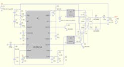
6. Draft compactly. Schematics aren’t printed as often as they’re viewed on the screen. But as even a 4K screen has nowhere near the resolution of even a $100 laser printer, the component values on the screen can be minuscule and difficult to read. However, if the drafting is compact, the component values on the screen will be readable without having to zoom in on one section at a time. Drafting compactly is so important in my own work that I will break the other guidelines. The figure below has ground symbols drawn at angles that don’t reflect current flowing from top to bottom in the interest of being compact.
Unnecessary Characters...or Nought?
The following convention addresses schematics specifically used for SPICE simulations:
7. Do not use unnecessary characters. Ever. It's just more clutter. Here are some examples:
i) Units. SPICE uses MKS and defaults to those units without users having the ability to specify any other units. A 3.3-V voltage source should have a value of "3.3"—not "3.3V"—since there’s no other possible unit system in SPICE. Similarly, the syntax is simply "PULSE 0 1 0 1µ 1µ .5m 1m" not "PULSE(0V 1V 0 1µs 1µs 0.5ms 1ms)"
ii) Parentheses. Traditionally, parentheses were alternative whitespace characters to SPICE parsers. However, in coding, they have special meaning. Don't use parentheses when the special meaning isn't what's meant.
iii) Commas. Commas were also treated as whitespace characters in early SPICE parsers. When people discovered that they were ignored, people wrote ".model dname D(Is=1e-13,Cjo=10p,N=1.1)" instead of ".model mydiode D Is=1e-13 Cjo=10p N=1.1" Don't use commas when their special meaning to modern compilers isn't what's meant.
iv) Meaningless zeros. Use ".1" instead of "0.1" Unlike humans, laser printers never miss the dot. The meaningless zero is just more clutter for your eye to parse before you can see the meaning. The leading zero makes no more sense than writing "1.0" for "1." No meaningless zeros.
v) Use metric multipliers, not scientific notation, because "1µ" is more concise than "1e-06".
Upcoming SPICEy Gigs
Electronic Design hosted a SPICE simulation webinar featuring the latest release of LTspice 24. To view the recorded webinar, click here.
Mike Engelhardt will be speaking on behalf of Qorvo and QSPICE at the Electronica trade show, Avnet Silica's booth in Hall B5, stand number 103 on Tuesday, November 12 from 4:00 to 6:00 PM. He will also be available during most of the exhibition at RFMW’s booth, Hall B4, Booth 503.
