Thermal Simulation Helps Solve Lead-Free Manufacturing Problems
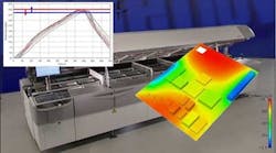
Version 3.0 of Flomerics'(www.flomerics.com) Flo/PCB thermal simulation software helps solve thermal problems in solder reflow processing associated with the use of lead-free solders. In particular, this tool addresses the challenge of controlling temperature variations across the pc board during the reflow process. This control is required to achieve the higher melt temperatures required by lead-free solders without damaging sensitive components. The new version of Flo/PCB can predict the temperatures at any point on the board during reflow.
This simulation makes it possible to optimize oven settings and thermocouple attachment points prior to a physical profiling run. It also allows board designers to investigate the effects of component layout on the solderability of the pc board assembly.
As the pc board is heated and then cooled while it passes through the reflow oven, the coldest component must be hot enough to melt the solder while all components must avoid exceeding the maximum component body temperature. Lead-free manufacturing makes this more difficult since lead-free solders melt at a higher temperature while the maximum temperature that components can be exposed to without damage remains the same. This means the temperature gradient, the difference between the maximum temperature experienced by the hottest part of the board and the maximum temperature experienced by the coldest part of the board, must be smaller than when traditional lead-based solders are used.
The temperature gradient is caused by the fact that not all components heat up at the same rate. Small components heat up more quickly than large components, and components that are close to each other also heat up more slowly than those that are far from other components. Components near edges and corners tend to heat up quickly. In addition, different package styles have different thermal response characteristics. Another factor that affects component heating rates is conveyer speed.
The maximum body temperatures defined by IPC J-STD-020 range from 245°C to 260°C while full liquidity with SnAgCu alloy solders is achieved only at 235°C. The temperature gradient over the board must thus be maintained within approximately 10°C.
Flomerics’ new Flo/PCB software makes it possible to design pc boards for lead-free manufacturing by predicting thermal gradients during solder reflow processing. Design engineers can evaluate the thermal gradients generated by different component layouts at an early stage in the design process when changes can be made inexpensively.
Manufacturing engineers can optimize oven settings such as conveyor speed and zonal temperatures to minimize thermal gradients. The coldest and hottest points on the pc board can be identified without the need for a physical test board. Furthermore, the oven calibration starting point can be predicted to minimize the number of profiling runs required.
