Microsoft’s Talisman: The Graphics Chip That Never Was
Series: The Graphics Chip Chronicles
In 1996, as the 3D graphics chip market was in its ascendency, with new companies declaring devices every month, Microsoft shocked the industry by introducing a radically different approach—tiling. The conventional architecture for a graphics chip had been (and still is) what’s known as an immediate mode pipeline. The tiling approach composites 2D sub-images to the screen.
Microsoft presented its new 3D graphics and multimedia hardware architecture, code‑named Talisman, at SIGGRAPH in 1996. Microsoft said at the time, “[it] exploits both spatial and temporal coherence to reduce the cost of high-quality animation.” The goals of this new technology approach were ambitious and startling:
- Desktop resolution: 1344 x 1024
- Display resolution: 1024 x 768
- Color depth: 32 bits
- Update rate (fps): 72
- 3D scene complexity: 20K+
- Z buffer resolution: 26 bits
- Texture filtering: anisotropic
- Shadows: filtered
- Anti aliasing: 4 x 4 sub pixel
- Translucency: 256 levels
- Audio/video acceleration: 1394, 3D sound integrated
- Input ports: USB integrated
Designed to overcome the limitations of the graphics pipeline of the time, Talisman dealt with graphics much differently than existing approaches. Instead of dumping data into a frame buffer, Talisman composed a scene that incorporates objects. It then stitched the separate objects (i.e., images, or tiles if you will) together, in a compositing process. In Talisman, individually animated objects were rendered into independent image layers which were combined at video refresh rates to create the final display.
During the compositing process, a full affine transformation (“morphing”) was applied to the layers to allow translation, rotation, scaling and skew to be used to simulate 3D motion of objects, thus providing a multiplier on 3D rendering performance and exploiting temporal image coherence. Image compression that was broadly exploited for textures and image layers to reduce image size and bandwidth requirements.
Talisman didn’t need to regenerate the total frame that changes in animation or video. Rather, it reused portions (tiles) of the frames, bending and warping the image—as long as it doesn’t change too much—re‑rendering it in imperceptible tenths of a second.
Microsoft Research had kept a low profile on the Talisman project since it started it in 1991 with just a handful of people working in basic and applied research. By 1996 the group had grown to over 100 members. At the time Microsoft wanted to be ranked among the top computer research labs in the country, along with such prestigious names as Bell Labs and Xerox PARC. In fact, 10 of the 52 papers presented at Siggraph 1996 were from Microsoft—a record number of papers accepted from any single company.
“Microsoft is not trying to make money on Talisman. We want to make money on the software once the entire industry leaps forward,” said Jim Kajiya, senior researcher of the group at the time.
Microsoft hoped Talisman would show up in late 1997 on motherboards and cards that support MPEG‑2 decoding, advanced 3D audio, videoconferencing, advanced video editing, and true-color 2D and 3D graphics at resolutions of 1024 x 768. That dream was never realized although a few companies tried. The company said with this design, performance rivaling high‑end 3D graphics workstations could be achieved at a cost point of two to three hundred dollars.
The design was based on four key concepts:
- Object-temporal rendering
- Priority rendering to specific objects
- Incremental approximations for intermediate frames
- Image compression used for textures and rendered images
- Advanced rendering techniques
- Polygon anti‑aliasing, anisotropic texture filtering, multi‑pass rendering (shadows, reflection maps)
- Integrated graphics, video, and audio
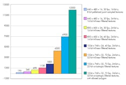
PC graphics systems designers struggle with three major problems: memory bandwidth, latency, and cost. However, to deliver compelling image quality and high entertainment satisfaction, greater than TV resolution is needed. Consider the impact this has on memory bandwidth at the time, as shown in the following chart:
Talisman used the concept of 3D objects, which are preprocessed into polygons and sorted based on their distance from the viewport. Then, the compositor chip would process the polygons on the fly, add texture‑maps to them and stream the pixels in real time to a special LUT-DAC.
There were four major concepts used in Talisman:
- composited image layers with affine transformation
- image compression
- chunking
- multi‑pass rendering
Talisman totally changed the flow of data through a 3D pipeline. In a conventional approach, geometry calculations would create a polygon list in main memory. Those polygons would be broken into spans of pixels. A 3D chip would read the pixel spans, calculate which pixels from each span would be visible, calculate lighting and save these intermediate results. The intermediate data would then be used by the chip to read texture maps from a dedicated texture memory and write modified texture data into a screen buffer.
Microsoft divided the processing tasks differently, as shown in the following diagram:
In the Talisman design there was no screen buffer, the rendering operations had to keep up with the LUT-DAC. To achieve that, tasks were assigned to the tiles and control logic many of which were new to the PC world.
The goals of composited image layers were:
- independent objects rendered into separate image layers (sprites)
- object images updated only when they change
- object image resolutions can vary
- sprites are alpha‑composited at display rates
- full affine transformation of each sprite at display rates
- 4x reduction in processing requirements
Overall control remained with 3D driver software running on the host CPU, but geometry calculation, lighting and Z‑sorting (operations normally done on the host in most PC‑graphics systems at that time) would be assigned to a new multimedia DSP chip being developed at Samsung. The DSP chip would process objects to produce a sorted polygon list in main memory.
Intel had traditionally and vigorously opposed the transfer of tasks from the CPU to another processor. However, at this point, Intel didn’t seem as concerned—they were busy with their SIMD MMX integrated co-processor, and denigrating RISC processors. At this time, Intel’s guiding principle was that X86 should rule. At the time there were some people who suggested Microsoft was working with Samsung’s chip out of a concern that Intel’s CPU road map didn’t offer enough compute power for compelling interactive 3D.
Talisman’s approach to 3D, like that of Nvidia’s chip based on quadratic surfaces, and VideoLogic’s PowerVR, was quite different from traditional solutions. Also, apart from Nvidia, there was no clear compatibility path for 2D graphics. Another critical point was the application had to be ported to the graphics controller to take advantage of the hardware, although Microsoft said at the time that Talisman would support the Windows D3D API, and therefore automatically compatible with the OS.
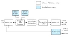
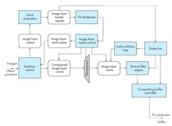
In a conventional frame‑buffer approach, the 3D hardware has one entire frame, typically one‑thirtieth of a second, in which to render all the visible polygons. If the chip falls behind in a particularly dense area of the screen, it can always catch up by going faster through a sparse area. Only the total number of rendered pixel spans really matters. The Talisman polygon object processor (also known as the “Tiler” chip) is shown in the following diagram.
Talisman’s rendering engine had to keep up with the LUT-DAC. No matter how dense the image, the row had to be rendered before the LUT-DAC needed the pixel data. When computing on the fly like that there’s no opportunity for graceful degradation.
The job of fetching polygons from main memory, breaking them down into spans and texture‑mapping them would be done by the compositor which was to be built by Cirrus Logic. The compositor worked on one macroblock (i.e., “tile”) of 32 x 32 pixels at a time, identifying which polygons would be visible in that macroblock and computing the textures for those polygons. The macroblock information was then forwarded to the intelligent Fujitsu LUT-DAC which drove the pixels onto the screen.
In an operation known as “chunking,” macroblocks could conserve graphics memory by splitting a picture into chunks, compressing, and computing each one separately. Storage requirements for images in chunks could be smaller by a factor of 60. That was the secret. Every graphics architecture is constrained and struggling against bandwidth limitations. Overcoming this bandwidth limitation was the key to getting high performance 3D. Talisman was able to perform multi‑pass rendering to generate reflections and shadows in real time.
There were several objectives for the chunking:
- each sprite is rendered in 32 x 32 chunks
- all polygons for a chunk are rendered before proceeding to next chunk
- allows 32 x 32 depth buffer to be on‑chip
- anti‑aliasing is supported with depth buffering and transparency using an on‑chip fragment buffer
- 32x reduction in frame buffer memory capacity requirements
- 64x reduction in frame buffer bandwidth requirements
The compositor connected to main memory via the AGP bus, which was the standard at the time and superseded by PCI. However, the bandwidth demands of the compositor were expected to be too high for the 66 MHz AGP. Therefore, Microsoft chose to use a JPEG‑like compression, which they called TREC to reduce the size of the texture map data stored in main memory. That means the compositor must do a TREC expansion on the fly along with its other tasks.
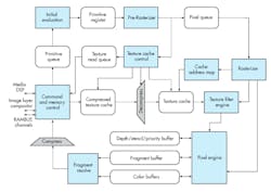
The image layer compositor was the other custom VLSI chip being developed for the reference hardware implementation. That part was responsible for generating the graphics output from a collection of depth sorted image layers. The image layer compositor is shown in the following diagram.
The image or sprite engine carried out several objectives:
- Performed addressing, filtering, and transformation of sprites for compositing
- 32 scan lines were processed together
- The data structure maintained a z‑sorted list of sprites (sets of chunks) visible in each
- There were 32 scanline regions
- The sprite engine performed affine transformations (scaling, rotation, translation [subpixel], and shear)
- Pixel and alpha data passed to compositing buffers at 4 pixels/clock cycle
Several benefits (and some cautions) came out of this new design:
- Color and alpha
- The default was 24 bits of color and 8 bits of alpha
- There was no performance advantage to using lower color or alpha resolutions. (However, using lots of alpha within a model, especially overlapping translucent polygons would slow the system. Overlapping models or sprites with translucency was adequate.)
- It compressed textures more than sprites (careful texture authoring gives best results)
- Texture filtering
- All textures had to be rectangular powers of two (256 x 256, 1024 x 32, 64 x 128, etc.)
- Tri‑linear mip‑mapping were available at full speed (40 Mpixels/second in reference implementation)
- Anisotropic filtering had a variable performance (1:1 ‑2:1 is at full speed, 2:1 ‑ 4:1 that was at half speed, 6:1 ‑ 8:1 was at fourth speed, maximum anisotropy was 16:1)
- There was no speed advantage for bi‑linear filtering or point sampling
- Shadows
- It used a multi‑pass rendering mode
- Shadows were created individually per object and light source (they could only be used sparingly, only for shadows such as important objects, and only from primary light source)
- Reflection mapping
- It used a multi‑pass rendering mode
- It requires rendering a low-resolution version of the scene from another viewpoint which (used processing time)
- It depended on reflective object, creation of mip‑maps may be required (used processing time)
- Scene complexity
- Object sprites could be used about 4 frames before re‑rendering
- It assumed 500K to 1M polygons/second rendered into sprites
- It allowed for audio and video
- Developers were advised to design for scalability and use LOD
Microsoft’s objective was to enhance the capability for the PC to deliver truly compelling entertainment experiences with display and sound quality beyond what was currently available from TVs. Some companies indicated they wanted to license it, and others were afraid they’d suffer severe competitive pressure because of it.
For example, Scott Sellers, a GPU architect, and founder of 3Dfx said at the time, “The fundamental problem we have with Talisman is the whole paradigm it forces software developers into. This is very much like the old image generators of the ‘80s that absolutely require software developers to keep up with the frame rate of the monitor. With the old image generators, when you found yourself in a scene in a flight sim that had too many polygons on it, and the CPU couldn’t keep up, the runway started to fall off. That’s exactly the problem Talisman is going to have. You must be fully optimized on Talisman before you really see anything running on the screen. It’s a really, really tough situation.”
Did we really need another 3D controller approach? Chip suppliers already had road maps full of 3D projects. Cirrus Logic’s third 3D engine was under development at the time, even though Cirrus didn’t expect to see significant benefits from their acquisition of 3DO technology — more on that in a future issue.
Did we need it? Yes. I agreed with Microsoft at the time — to get the consumer excited about entertainment on the PC there had to be compelling content, and 30 fps at 640 x 480 just wasn’t going to do it.
Epilogue
The tiling approach was later adopted by all but one of the mobile GPU suppliers and IP providers, and the one who didn’t abandon the market. Today every smartphone and tablet have a GPU with a tiling engine, and every PC still uses immediate mode GPU processing.
Microsoft didn’t invent tiling. The early work on tiled rendering was done as part of the Pixel Planes 5 architecture (1988). The Pixel Planes 5 project validated the tiled approach and invented a lot of the techniques now viewed as standard for tiled renderers. It is the work most widely cited by other papers in the field.
The tiled approach was also known early in the history of software rendering. Implementations of Reyes rendering often divide the image into tile buckets.
Why was it never adopted?
Several factors that were in motion at the time. Remember, the project was started in 1991 and at that time, the impact of Moore’s law wasn’t fully appreciated. As a result, CPUs got faster, RAM increased in capacity, and speed, while dropping in price, and overall bandwidth increased. Added to that Microsoft introduced DirectX, Windows stabilized, and Windows 95, which supported higher resolutions was introduced. Games became more efficient, and first-person shooters became popular. So, tiling wasn’t a good choice for PCs and workstation, but as mentioned, ideal for power-starved mobile devices.
