Deploying a Digital Magnitude/Identity Comparator
Members can download this article in PDF format.
What you’ll learn:
- How an Identity comparator functions.
- How a Magnitude comparator works.
- Creating a digital comparator circuit.
Digital comparison is considered an important method used in digital systems while executing arithmetic or logical operations. It’s designed to compare the relative magnitudes of binary numbers. This comparison is used to test whether one number represented by one binary word is greater than, equal, or less than the other number. Two main types of digital comparators are available—an Identity comparator and a Magnitude comparator.
This article discusses the implementation of an 8-bit Identity comparator and a 4-bit Magnitude comparator, covering both the concept and the circuit design. We used an Arduino program to execute an automatic test for this design. The program presents all possible binary combinations to the GreenPAK comparator inputs and checks the matching output.
This implementation is based on the GreenPAK SLG46533 IC. This circuit was chosen because it contains all of the necessary components. Furthermore, the IC helps reduce the cost of the solution, and it can be programmed within minutes in free GreenPAK Designer software.
8-Bit Identity Comparator
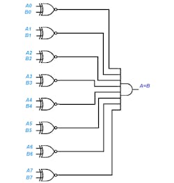
An Identity comparator is a digital comparator with only one output. It goes high when A = B, either both 1s (High) or both 0s (Low). This comparator can be implemented by a combination of logic gates (XNOR and AND gates) (Fig. 1).
With 8-bit numbers, the comparator compares each bit of the number with an XNOR gate. Two 8-bit numbers are only equal if each bit is identical.
- Inputs: The bits of two numbers that need to be compared (A, B), 8 bits for each number.
- Outputs: One output terminal that goes High if A = B.
The Identity comparator’s circuit consists of an exclusive NOR gate (XNOR) per pair of input bits. If the two inputs are equal (both logic 1 or both logic 0), then a logic 1 is output. The outputs of the XNOR gates are combined in an AND gate, the output of which will be high only when all XNOR gate outputs are high (XNOR inputs are matched).
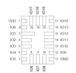
The circuit requires 18 pins: 8 pins as inputs for the first number (A for example), 8 pins for the second number, a single output that goes High at its output if both numbers are equal (otherwise it’s low), and an Enable input to activate the circuit. The GreenPAK SLG46533V has 18 inputs/outputs in addition to 25 blocks that can be configured to operate as logic gates. It’s therefore suitable for constructing the circuit's functions.
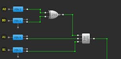
The logic function XNOR is considered responsible to detect the similarity of the bits, i.e., its output gives a logic 1 if the two bits at the input are equal (whether 0 or 1). Therefore, the XNOR gate is a 1-bit comparator. The complete comparator has been built in the form of sections, which means a 1-bit comparator was constructed using a XNOR gate. The XNOR output was then connected to a 3-bit lookup table (LUT) to create a 2-bit comparator. This process has been repeated four times with the aim to create four 2-bit comparators.
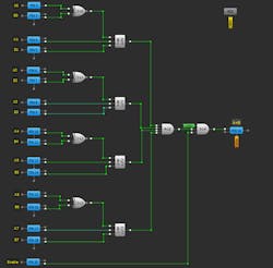
The outputs of those four comparators were connected to a 4-bit AND gate to build an 8-bit comparator, where the final result is obtained through PIN19, while PIN20 is an Enable input (Fig. 2).
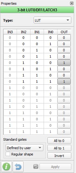
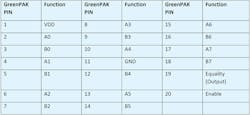
Figure 3 shows the 3-bit LUT0 configuration, and Figure 4 illustrates the Identity comparator design. Table 1 lists the pin numbers and the function matching each pin, where PIN19 is the circuit's sole output.
4-Bit Magnitude Comparator
The Magnitude comparator circuit compares two digital or binary numbers (consider A and B) and determines their relative magnitude. It also can be used to indicate equality, but has two additional outputs—one that’s logic 1 when word A is greater than word B, and another that’s logic 1 when word A is less than word B.
Three binary pins are used to indicate the output of the comparison as A > B, A < B, or A = B.
Figure 5 shows the block diagram of a 4-bit comparator that compares the two numbers of 4-bit length. Its output indicates the relationship between A, B.
The comparison process starts by comparing the most significant bit (MSB) first in comparing 4-bit binary numbers. If equality A = B exists, then the next lowest bit is compared and so on until it reaches the last bit (LSB). If equality still exists, then the two numbers are considered equal.
Otherwise, if inequality is found, either A > B or A < B, and the relationship between the two numbers is determined and the comparison between any additional lower order bits is ignored.
The output logic statements of this comparator are:
If A3 = 1 and B3 = 0 ---------> A is greater than B (A>B). Or
If A3 = B3, and A2 = 1 and B2 = 0, --------> A > B. Or
If A3 = B3, A2 = B2, and A1 = 1, and B1 = 0 ---------> A > B. Or
If A3 = B3, A2 = B2, A1 = B1, and A0 = 1 and B0 = 0 --------> A > B.
The output A > B logic expression can be written according to the above statements as:
G=A3 B3' + (A3 XNOR B3) A2 B2' +(A3 XNOR B3) (A2 XNOR B2) A1 B1' + (A3 XNOR B3) (A2 XNOR B2) (A1 XNOR B1) A0 B0'
In a similar way, the logic expression for the L (A < B output) can be written as:
L= A3' B3 + (A3 XNOR B3) A2' B2 + (A3 XNOR B3) (A2 XNOR B2) A1' B1 + (A3 XNOR B3) (A2 XNOR B2) (A1 XNOR B1) A0' B0
The equal output turns high when all individual bits of one number exactly matches the corresponding bits of another number. Then the logic expression for A = B output is written as:
E = (A3 XNOR B3) (A2 XNOR B2) (A1 XNOR B1) (A0 XNOR B0)
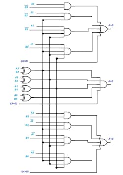
According to the above output Boolean expressions, the circuit of this comparator can be implemented by using standard logic gates as shown in Figure 5. Here, the four outputs from XNOR gates are then combined in an AND gate to give the binary variable E (A = B). A > B and A < B outputs also use XNOR outputs to produce the functional results as shown.
- Inputs: The bits of two numbers that need to be compared (A, B), 4 bits for each number, I2C pins, cascading inputs if connecting two ICs for comparing 8-bit numbers.
- Outputs: Three output terminals, one each for equality (A = B), greater than (A > B), and less than (A < B).
GreenPAK Design
The design consists of three sections:
- The first is responsible for detecting that the A > B condition was found.
- The second is responsible for examining that equality (A = B) was found
- The third has the task of checking that the A < B condition was reached.
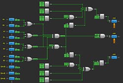
The blocks 2L0, 2L1, 2L2, and 2L3 were configured to operate as XNOR gates that compare the pairs of bits of both numbers and detect equality.
The blocks 3L0 ,3L1, 3L2, and 3L3 detect whether the A > B condition was attained, where A3 and B3 are tested at the outset through 3-bit LUT0. If A3 > B3 (i.e., A3 = 1, B3 = 0) a High signal appears on PIN17. However, if they’re equal, there will be a move toward the less significant of two bits A2, B2 and a comparison occurs via 3-bit LUT1, and so on for the rest of the bits.
The blocks 3L5,3L14, 3L15, and 3L16 check if A < B condition was fulfilled as the previous method is repeated, but concentration this time will be on A > B (i.e., Ax = 0, Bx = 1).
The design has been equipped with pins for cascading, enabling several circuits to be connected together. Also, numbers greater than 4 bits could be compared.
These inputs are examined for the case of an A = B condition for all higher-significance inputs of the circuit. Consequently, there’s a move toward the lower significant bits of the other circuit for holding a comparison.
According to the result of such comparison, the result for the whole-number comparison is taken via the higher-significant outputs of the circuit. The cascading bits are tested using the blocks 3L3, 3L12, and 3L6 as illustrated in Figure 6.
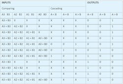
Table 2 represents the truth table for the final circuit of the Magnitude comparator.
Table 3 shows a GreenPAK PINs map of a Magnitude comparator, while Figure 7 reveals an SLG46533V PINs schematic.
Comparators in Cascade
An 8-bit comparator can be built by cascading two 4-bit comparators to compare two 8-bit numbers. Figure 8 shows the circuit connection of this comparator, in which the outputs of the lower-order comparator are linked to the respective cascade inputs of the higher comparator I (A < B), I (A = B), and I (A > B).
A High signal must be connected to the A = B cascade input of the lower comparator, while the other two cascading inputs, A < B and A > B, must be connected to a low signal. This also applies to a single IC if only two 4-bit words are being compared. The result of the comparison appears on the three outputs of the higher-order 4-bit comparator.
To make sure that the design operates properly, an external microcontroller circuit was employed to carry out an automatic test for all of the possible cases to which such a circuit might be subject. The comparator contains eight inputs, four for each number. Hence, the number of the cases that could be created is 256.
A program has been written for an Arduino board and it was connected to the final design. The program’s function is to generate all possible binary formations for the inputs, read each case's output, and verify its correctness. Figure 9 shows a serial monitor after testing.
Conclusion
In this article, we described two types of digital comparator circuit designs: Identity and Magnitude. The GreenPAK IC has exhibited high efficiency in terms of the construction of the desired digital circuits. In addition, the circuit is quick to design and low cost, and it delivers a complete tested IC.
The GreenPAK design was created in the free GUI-based GreenPAK Designer software, a part of Go Configure™ Software Hub, (link to the design file).

