What’s the Difference Between CXL 1.1 and CXL 2.0?
Members can download this article in PDF format.
What you’ll learn:
- Explore fundamental capabilities of CXL
- Understand the primary differences between CXL 1.1 vs. CXL 2.0 and the enhancements made as the protocol natively evolves
- Explore managed hot-plug, memory QoS telemetry, speculative reads, and security enhancements.
Compute Express Link (CXL) is a cache-coherent interconnect, designed to be an industry-open standard interface between platform functions such as processors, accelerators, and memory.
CXL 1.1 is the first productized version of CXL. It brings forward a world of possibilities and opportunities to improve upon the many strong features that exist in the PCI Express (PCIe) arsenal. The specification introduces the concept of memory expansion, coherent co-processing via accelerator cache, and device-host memory sharing.
The rich set of CXL semantics goes much beyond the familiar cxl.io (PCIe with enhancements) to also offer cxl.cache, and cxl.mem. These semantics are groups into Device Types: 1 (cxl.io/cxl.cache), 2 (cxl.io/cxl.cache/cxl.mem) and 3 (cxl.io/cxl.mem).
Given the disruptive nature of CXL, its true value and potential ecosystem of applications are yet to be realized once it’s deployed at scale. As the standard evolves, CXL 2.0 builds upon CXL 1.1 and uncovers new opportunities to further strengthen the robustness and scalability of the technology, while being fully backward compatible with CXL 1.1.
In this article, we’ll explore the fundamental capabilities of CXL and highlight the primary differences between CXL 2.0 vs. CXL 1.1, as well as the enhancements made as the protocol natively evolves.
Topology Structure: From Direct Attachment to Switching
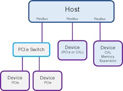
CXL 1.1 uses a simple topology structure of direct attachment between host (such as a CPU or GPU) and CXL device (such as CXL accelerator or CXL-attached memory) (Fig. 1). FlexBus ports on the Host Root Complex use standard PCIe electricals and can support native PCIe devices (optionally over a switched PCIe topology) or CXL devices (direct attached only).
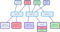
CXL 2.0 further elaborates the topology structure by introducing a new single-level CXL switch entity that provides a topology fanout of multiple devices (CXL or PCIe) connected to multiple hosts in a “mix and match” fashion for further expansion. This CXL Switch can be configured using an FM (Fabric Manager) that allows for each Host to get a different subset of CXL Devices.
With CXL 1.1, each device was able to connect only to a single host. With CXL 2.0, a CXL switch enables each device to connect to multiple hosts, allowing for partitioning or demand-based provisioning of resources. As a result, completely separate virtual CXL hierarchies can be created, where each host sees a virtual CXL switch beneath it and is led to believe that all of the devices it sees are its alone.
CXL 2.0 Logical Devices: SLD and MLD Resources
With CXL 2.0, multiple Hosts can be connected to a single CXL device, and oftentimes it make sense to split the resources of such a device unto multiple Host recipients. To do this, a supporting CXL MLD (Multi Logical Device) can be split into up to 16 x LDs (Logical Devices) identified by separate LD-IDs (Fig. 2). Each of the LDs can then belong to a separate VH (Virtual Hierarchy), have separate reset controls, and be handed out by a CXL switch to a particular host as though it was a separate resource.
For example, a CXL MLD memory expander that has 64 GB of DRAM and 256 GB of persistent memory (PMEM) could be split into up to 16 isolated LDs, with some LDs exposing DRAM resources and other LDs exposing PMEM resources. In this way, a host requiring additional memory could connect to LDs providing either DRAM or PMEM as needed.
CXL 2.0 supports only Type 3 MLD components, which may represent memory resources or any other acceleration resources that are split and provisioned over time and into sets of capabilities.
Fabric Management: Controlling the Elaborated Topology of CXL 2.0
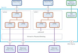
The elaborated topology structure of CXL 2.0 that introduces CXL switches and MLDs makes a lot of sense when controlled by an FM (Fig. 3). The FM sits external to the CXL switches and configures the internal CXL hierarchies within them.
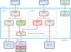
Each CXL hierarchy is defined by a Virtual CXL Switch (VCS) within the switch so that a host is completely isolated from all other hosts. This is done by configuring internal virtual PCIe-to-PCIe bridges (vPPBs) and binding them to physical PCIe-to-PCIe bridges (PPBs) that attach directly to CXL devices (Fig. 4). In favor of simplicity, CXL 2.0 also provides a static configuration that doesn’t require an FM in the case where only SLDs are present.
The FM can boot alongside the hosts, or before them, and execute changes to the bindings of physical devices to VCS in real-time.
In addition, the FM can take any form, including software running on a host machine, embedded software running on a BMC (Baseboard Management Controller), embedded firmware running on another CXL device or CXL switch, or a state machine running within the CXL device itself. Using a standardized API, the FM can send commands to LDs gathering error information, quality of service (QoS), and bandwidth information.
Resource Pooling Becomes a Reality with CXL 2.0
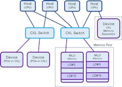
CXL 1.1 introduces Memory Expansion in the form of a CXL memory device (normally a Type 3 but can also be Type 2) directly attached to a particular Host. With CXL switching and MLDs in CXL 2.0, comes an entirely new world of Resource Pooling possibilities, such as Memory Pooling (Fig. 5).
Memory pooling allows every host to access all of the memory that it needs, dynamically on-demand, from a centralized large pool or from a set of pools. The memory pool may be composed under a CXL switch spanning multiple CXL devices; each may be an MLD providing different memory resources. Similarly, multiple hosts may allocate accelerators on-demand from an Accelerator Pool.
CXL 2.0 Managed Hot Plug: Enabling On-Demand Provisioning
Large systems with multiple hosts, switches, and Devices hold resources that can be provisioned on-demand and require methods of connecting and disconnecting these resources. It doesn’t make sense to turn off the system every time a new device is added, as it may require turning off a whole fleet of systems. Along with CXL switches and FMs, CXL 2.0 introduces the concepts of Hot-Add and Managed Hot-Removal.
The Hot-Add feature leverages the baseline scheme defined in PCIe with modifications to allow for all of the new CXL capabilities. But unlike classic PCIe systems, the addition of cache coherency and memory requires special attention. Therefore, device removal needs to be done using software request. This gives the host the ability to flush any modifications and read-back or propagate memory.
Memory QoS Telemetry
CXL provides QoS telemetry (DevLoad) methods, some optional and some mandatory, that enable the host to throttle and balance work request rates based on returned load telemetry. This opens the door to dynamic load balancing and intelligent memory mapping. With the addition of MLDs in CXL 2.0, QoS can be associated with a LD and allow memory devices to share load levels per resource.
CXL 2.0 Speculative Memory Reads
Speculative memory read is a new command introduced in CXL 2.0 to support latency saving. The command hints a memory supporting device to prefetch a data for a possibly imminent memory read from the host.
Memory Interleaving
CXL 1.1 supports a basic interleaving method on multi-headed devices when a cxl.mem device is connected to a single host CPU via multiple FlexBus links. CXL 2.0 enables interleaving across multiple devices using physical address bits 14-8, allowing for IG (Interleaving Granularity) of different sizes. Every interleave set contains 1, 2, 4, or 8 devices.
CXL 2.0 also introduces a LSA (Label Storage Area). LSA allows both interleave and namespace configuration details to be stored persistently on the device to preserve geometry configurations in a similar fashion to RAID arrays.
Security Enhancements
While CXL 1.1 allows for proprietary security measures defined by hosts and devices, CXL 2.0 takes a more constructive approach. Leaning on the SPDM (Security Protocol and Data Module) defined by DMTF (Distributed Management Task Force), CXL 2.0 adopts a comprehensive set of rules leveraged from PCIe IDE for a secure connection relying on AES-GCM cryptography.
Wrap Up: What's the Difference?
CXL is a new frontier, enabling a fundamental wave of innovation in data-center-related technologies. Whereas CXL 1.1 focuses on enhancements within the server platform, such as Memory Expansion, CXL 2.0 goes out and beyond the server platform to define system-wide solutions such as Memory Pooling that serve multiple server platforms. CXL 2.0 further strengthens the RAS (Reliability, Availability and Serviceability) capabilities of the protocol that become even more important as the system span of CXL expands to larger diameters with CXL 2.0.
The CXL Consortium is working diligently to augment and strengthen the CXL ecosystem and bring new capabilities that will enable higher scalability, performance, and efficiency. Stay tuned for the next-generation CXL specification coming this year.

