What’s Trending in SOSA-Aligned OpenVPX Chassis?
This article appeared in Microwaves & RF and has been published here with permission.
This article is part of the Library Series: Rugged Systems.
What you’ll learn:
- Who is SOSA and what do they provide?
- Types of OpenVPX designs.
- Heat-dissipation methods.
Products emanating from the Sensor Open Systems Architecture (SOSA) consortium continue to gain traction in the Mil/Aero embedded-computing market. A primary goal of SOSA is to limit the wide variation of MOSA (Modular Open Standard Architecture) designs to a more manageable level. The benefits to the military (at least theoretically) are ease of integration, less training time, a more plug-and-play ecosystem, less confusion, less vendor lock, lower costs, and more. It also gives them the ability to have a more manageable innovation process.
By proving the military’s design goals at the front end, this helps the engineering groups in the open standard committees to come up with appropriate solutions. This hand-in-hand approach keeps the design community focused and solutions-oriented.
SOSA is primarily focused on 3U and 6U OpenVPX-based open standard systems, but other specialty architectures are also emerging. SOSA is leading the “demand” for certain routing profiles for the backplane that accept certain slot profiles for the OpenVPX boards. From a chassis platform perspective, SOSA’s efforts are driving the backplane speed requirements, hotter plug-in cards that require more advanced cooling solutions, the RF and fiber interfaces that lead to new I/O solutions, and chassis management.
Backplanes for SOSA-Aligned Systems
Backplanes requiring 100 GbE (4 lanes of 25 Gb/s) and often PCIe Gen4 (16 Gbaud/s) are common for SOSA-aligned systems. However, 40 GbE is often acceptable. The backplanes will typically have fiber and/or RF interfaces.
We’re seeing clear delineations of which versions (NanoRF, SMPN, MT options, etc) that are commonplace. The NanoRF is particularly notable as it offers up to 20 RF interfaces along with MT fiber and comes in various mixes/configurations. The MT ferrule options are expanding from the supplier base with 3 MT and even 4 MT options (which typically have 12- and 24-fiber options) that fit into the standard VITA 67.3c or VITA 66.1 envelop size, respectively.
Chassis Cooling
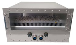
The high-wattage systems are driving more advances in cooling. A 19-in. Mil rugged rackmount chassis (Fig. 1) can be designed to hold up to 16 slots of VITA 48.2-compliant conduction-cooled boards. With special card mats, the heat is dissipated to the fins where airflow can be applied with Mil-grade fans to cool the fins. The approach as a rule of thumb can cool approximately 100 W/slot.
In a fully loaded 16-slot system, a mezzanine-based chassis manager can affix to the rear of the backplane, so that it doesn’t consume any slots. The “Tier3+” SOSA-aligned chassis manager can monitor/control intelligent fans and SOSA VITA 62 power-supply units (PSUs), provide graceful shutdown and sequenced initialization of plug-in boards, and much more. The specification requires the use of a SOSA-aligned chassis manager in the enclosure platform.
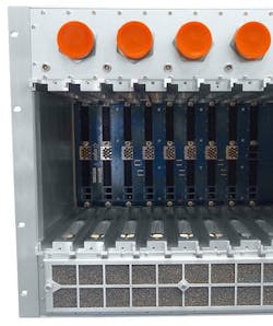
Similarly, this approach can be utilized in an ATR format enclosure. The ATR (Fig. 2) can also be designed with special I/O interface boards both on the front and rear of the enclosure to provide more I/O space. It should be noted that not all applications would allow this type of configuration.
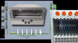
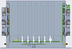
For even hotter system requirements, there are newer airflow approaches (Fig. 3) such as VITA 48.7 (Air Flow By) with airflow over the fins of the plug-in cards, VITA 48.8 (Air Flow Through), and new concepts meant to optimize slot spacing with similar approaches. Liquid cooling is often the last resort with its own complications, high costs, smaller ecosystem, and infrastructure requirements. However, some of the high-end SOSA designs (and future aspirations) seem to make the use of liquid cooling inevitable.
I/O Considerations
As discussed, in the unit in Figure 1, these applications sometimes require a wealth of I/O interfaces. While SOSA may limit some of them (or shift more to fiber, etc.), many designs have almost more I/O than space is available by typical means.
One potential solution is the use of a special serial multiplexer board that provides for the condensing of multiple serial ports into one compact interface. This type of design can save significant I/O panel space in a chassis platform.
In this example, a single USB 2.0 Micro interface on the multiplexer mezzanine board allows for 28 UART connections, two USB interfaces, and a chassis manager interface on a board that measures approximately 50 × 112 mm. The board can be mounted to the rear of a backplane like a mezzanine in the same type of approach as the SOSA-aligned chassis manager described earlier.
An Exciting Future
While SOSA applications look to have a bright future, a wealth of other designs still don’t need to meet those requirements. As mentioned, SOSA has many benefits, but it can be overkill, or conversely, too restrictive for many design needs. It will be exciting to see the continued evolution of SOSA and other MOSA technologies for Mil/Aero applications.
Read more articles in the Library Series: Rugged Systems.


