This file type includes high resolution graphics and schematics.
AdvancedTCA (ATCA) is a compelling application-ready hardware architecture for many systems and markets. It combines the benefits of Eurocard’s rugged and well known structure with high-bandwidth performance for the most intensive applications in communications, military, scientific, and advanced computing designs. Offering the most cores in the least space in a fault-tolerant environment, ATCA can reduce costs and time-to-market.
The ATCA design requires careful considerations to offer strong performance in signal integrity, thermal management, and electromagnetic compatibility (EMC). With 40G on the rise and goals of 100G solutions on the drawing boards, balancing these counter-affecting elements creates additional challenges. As signal speeds rise using faster (and hotter) chipsets, the pressure increases on the cooling requirements. EMC containment and the aperture holes for cooling have an inverse relationship.
Table Of Contents
- AdvancedTCA
- The Reality Of 40G/400-W ATCA Systems
- Fast
- 10G To 40G To…?
- Cooling The Chassis To 400 W
- Power Overload
- Vertical Vs. Horizontal
- ATCA’s Future
AdvancedTCA
What are system designers looking for in developing a new system? Ultimately, they tend to be maximizing the computing density for the price and performance requirements of a particular market or application. When we talk about higher speeds, we are talking about the higher bandwidth within the same or decreasing enclosure envelope size. In general, faster processors require more power and dissipate more heat. Less space or increased density typically means more heat and greater challenges to achieve fault tolerance.
ATCA systems are now designed to 40G speeds (10G by eight lanes) across each full duplex channel, which enables high-speed scalability of 10 Tbits/s. Furthermore, its bladed architecture permits processing capability to scale over time based on network demand and growth. A 14-slot vertical-mount shelf (in 13U-15U height typical) provides for speeds of multiple terabits/shelf. However, cooling these ultra-hot Sandybridge, Ivybridge, and other processors is putting increasing pressure on the designs.
The Reality Of 40G/400-W ATCA Systems
If you’ve been following ATCA, you certainly have seen 40G ATCA systems. You may have even heard a bit about cooling up to 400 W with forced air. But the cooling needs to be balanced for EMC, acoustic noise, and handling power entry requirements in the given space. The speed and cooling for these systems can be challenging. Balancing all of these factors, particularly for Network Equipment Building Standards (NEBS) or environmental compliance, is even tougher.
Related Articles
• Whitepaper: Storage Strategies For AdvancedTCA Platforms
• 40G ATCA Backplanes Rely On IEEE Standards
• Leverage AdvancedTCA to Optimize IMS
First, let’s clarify what we mean by 400-W cooling. From our standpoint, we are talking about 400-W cooling/slot in the front card slots. With a 14-slot system, this is over 6400 W in the front cards alone. The rear transition module (RTM) area is separate, with an additional 75 W/slot minimal. This brings the total system cooling to over 7 kW in a 15U space. Also, we are talking about still meeting NEBS compliance and Communications Platform Trade Association (CP-TA) guidelines, including all redundancies and de-ratings, ability to cool with a field replaceable unit (FRU) removed for two minutes, and other standards. If you aren’t taking in all of these considerations, you aren’t comparing apples to apples. CP-TA is now part of the PCI Industrial Computer Manufacturers Group (PICMG).
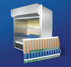
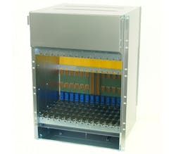
The original PICMG 3.0 specification developed in 2002 required 200-W/slot cooling for both front and RTM blades. The expected RTM area was only 15 W/slot. Today, the cooling requirement for the front slots has doubled and the RTM has more than quadrupled! So, how do we achieve this cooling? First, let’s look at what was designed back in 2002. The 13U ATCA chassis was perhaps the most commercially deployed ATCA design in history with more than 15,000 global installs (Fig. 1). With a 13U height, it cooled 270 W/slot with RTM shelf managers and 4x power entry modules (PEMs). The backplane was designed to the then standard 10G speeds (3.125 Gbits/s/8 lanes).
Fast Forward
Eleven years later, the ATCA architecture’s market share is in the billions of dollars. The specification was originally geared for telecom central office applications. Since then, it has been expanded to data center, scientific/research, specialized high-end computing, and military applications. ATCA recently has enjoyed increased deployments in benign environment military/aerospace applications where the tremendous bandwidth, low cost, and large ecosystem of hardware manufacturers is a significant plus.
One example is the mobile communications trailer or command center to accept the massive data from network-centric warfare. ATCA is even being adopted (with modifications) in some applications with more ruggedized applications. Military/aerospace designers need to consider that ATCA was designed for telco central offices in controlled environments. So, operating temperatures, shock/vibration levels, and battling the environmental factors should be reviewed closely. But, there is a niche of ruggedized ATCA enclosures being deployed today.
10G To 40G To...?
The backplane for ATCA is also becoming significantly more challenging. One of the first full-mesh 14-slot backplanes was developed as 36 layers using Nelco 4000-13SI with 3.125-Gbit/s speeds across eight pairs for 10G signaling. Later, customers utilized dual-star topologies, and vendors over time were able to reduce the layers and utilize standard FR-4 material.
Borrowing from the IEEE 802.11b specifications, ATCA Rev 3.0 offers 40G (8 by 10G) signaling today. But with simulation and testing, one can offer proven performance at 16 layers without the need for expensive back drilling or the need for blind and buried vias. Materials being used range from Nelco4000-13SI to Panasonic’s Megtron 6 to FR-4. Dual-dual-star configurations with four hub slots are also starting to be designed for 40G ATCA.
The 100G level is a concept that is on developer’s minds, and some research projects are planning even more aggressive goals. But, silicon today does not meet this challenge. It took about 10 years for the standard to go from 10G to 40G, including all of the testing, interoperability, silicon, hardware, and software development required. This allowed the ecosystem to gain adoption, rather than wait for the “next big thing.” I doubt it will be more than half that long for 100G, but this is another paradigm shift where the whole ecosystem would need to change.
This file type includes high resolution graphics and schematics.
Going back to today’s 40G rates, which address the growing demand for packet processing, inspection, and filtering applications, the higher frequencies that are being generated also bring up environmental concerns of adequate electromagnetic interference (EMI) shielding. One way to contain EMI is by reducing the airflow aperture holes. Of course, this reduces air intake and increases static pressure.
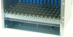
With up to 400 W/slot to cool, the right balance is critical. One solution is to utilize an EMC mat below the card cage, which spreads the air impedance over the width of the chassis, but catches any emissions before they enter/exit the card cage. The shape/design of the EMC mat can also help with airflow patterns (Fig. 2). Thus, you’re killing two birds with one stone.
Cooling The Chassis To 400 W
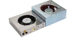
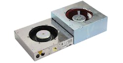
As mentioned, the lightning fast processors are pushing the cooling requirement to 325 W/slot or even more in some cases. In some applications, customers are asking for up to 400 W/slot! For a vertical-mount shelf, which can hold 14 slots plus two shelf managers in “Slot 0” of the card cage of a 19-in. rack-mount shelf, this is a challenging task. When approaching these heat levels, the 13U size has its limitations. With 325 W/slot, even advanced cooling solutions for ATCA have some difficulty. Putting in heavy-duty air movers helps the cooling (Fig. 3).
However, pushing that amount of airflow in the smaller space causes significant dynamic pressure. The EMC mat solution gives a designer the flexibility to focus adjustments to the hole sizes on the exhaust area and balance cooling within proper radiated emissions levels. But that can only take you so far. Many equipment providers are concerned with service availability and require the shelf to operate under normal conditions with an FRU removed for more than two minutes. You will probably start to see problems in the 13U size trying to reach the 400-W mark.
By increasing the enclosure height, the designer can increase the exhaust rate, have a larger air plenum to overcome FRU failure conditions, use heavier-duty air movers, and perhaps most importantly alleviate the dynamic pressure. The result is a significant boost in cooling capability. For the 15U ATCA chassis, an outcome of cooling above 400 W/slot in the front plus 50- to 75-W or more in the RTM area is achievable while meeting NEBS compliance and CP-TA guidelines (Fig. 4).
Power Overload
Another consideration in high-performance ATCA systems is the power requirement. The chassis provider needs to provide power for up to 475 W a slot (i.e., 400 front + 75 rear). There also needs to be redundant feeds. So, all FRUs need to have redundant A&B power. The chassis must be able to deliver this power, approximately 12 A, while complying with UL 60950-1.
The power entry modules utilized in the chassis need to attenuate any noise both to and from the chassis. At minimum, these modules need to attenuate 18 db over 150 kHz to 1 MHz. Proper filtering is required to meet today’s environmental conducted emissions. Some systems have a combination of FRUs operating at 3.3 V, 5 V, 12 V, and normal operating voltages.
There also needs to be de-rated power for cooling. It is challenging to meet cooling requirements with most fans designed for optimal operation at –48 V. However, by definition, normal operating conditions range from –40.5 V, and most fan performance is significantly decreased at this voltage.
Thus, it is important to test fault tolerance at the bottom of the voltage range to ensure compliance. Double pull breakers can be used for equipment protection. Chassis providers need to consider a combination of the PICMG specifications, telco requirements, and datacenter requirements to implement 380-V power to improve efficiency and decrease transmission loss.
Vertical Vs. Horizontal
Thus far, we’ve been talking about a vertical-mount shelf in 14-slot sizes. But in many applications, the 14 slots aren’t fully subscribed. To maximize performance density, it would be ideal to have a smaller slot count and be able to scale up with more shelves as needed. In fact, you can fit only two 15U shelves in an industry-standard 42U rack. With a 6U shelf, you can fit theoretically seven shelves, although six may be more practical to hold other equipment.
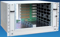
The 40G ATCA performance in horizontal-mount shelves can also be highly compelling for datacenter, military/aerospace, and other high-density computing applications. Small stackable 3U ATCA shelves with two slots have been popular in many networking/datacenter applications due to their small size and scalability. A 6U height shelf with six slots should be an attractive size.
One of the prior hurdles for widespread acceptance of a 6U height was that in a dual-star configuration, two slots are dedicated for hub slots. So, you are left with only four payload slots. Today, we can combine the shelf manager and the hub in one module. With the hubs on the shelf managers, which are located right below the main card cage, the system offers a full six payload slots. This is a 50% increase in computing density. The shelf can also utilize either ac power with the PEMs located below the shelf managers or 48-V dc direct terminals.
Going back to our example of six 6U shelves in a 42U rack, this would allow 36 payload slots in a rack (6 by 6). It would be 42 payload slots if you squeezed in the seventh shelf. That’s one ATCA blade per 1U. Compare this to the 15U ATCA where you would get 24 payload slots (12 + 12) in the 42U rack. That’s 1.75U per one ATCA blade. Even if you had a 45U rack for three 15U shelves, you would have 36 payload slots per rack or 1.25U per blade. A 14U size can be attractive as three fit in a 42U rack. But again, this allows zero space for other equipment, and the cooling/performance requirement needs to be in the sweet spot between the 13U and 15U sizes.
But can such a vertical-mount shelf with side-to-side airflow cool the 325+ W/slot of today’s boards? Yes, more than 350 W/slot is achievable following the CP-TA defined requirements including a 0.6-in. impedance curve rating for your fans. Engineers should be careful of any claims out there and how they are defined. In this example, 350 W is just for the front cards. The SlotSaver format shelf has two fans dedicated in the rear on each side of the card cage for up to an additional 45 W/slot of cooling in the rear I/O area (Fig. 5).
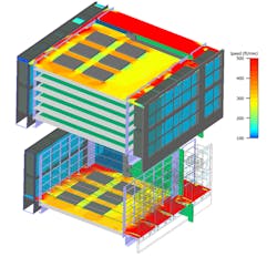
Of course, to meet high availability requirements, these types of ATCA shelves have removable, pluggable fan trays with separately removable filters, swappable ac power supplies (or ac-dc or dc-only versions), etc. Thermal management simulation allows designers to locate hot spots or problem areas so they can make adjustments (Fig. 6). Another consideration is that many applications require front-to-back cooling, so special horizontal-mount versions in this airflow configuration with the combined switches/shelf managers are in development.
ATCA’s Future
AdvancedTCA continues to provide increasingly compelling performance density as we have moved to 40G solutions. The high availability, proven reliable design, and ability to handle faster and hotter processors makes ATCA an attractive architecture. With creative cooling solutions and chassis/system designs that redefine computing density, ATCA shelf solution providers continue to rise to the challenge.
Justin Moll is the vice president, U.S. market development, at Pixus Technologies (www.pixustechnologies.com). He has a BS in business administration and management from the University of California, Riverside. He can be reached at [email protected].
This file type includes high resolution graphics and schematics.
