This article is part of the Ideas for Design Series: Vol. 3, No. 8.
In many applications, accurately sensing the position of an electrically controlled mechanical device such as a motor is critical. While many published designs require additional hardware components and thus increase cost, this approach uses the general-purpose input/output pin interrupt and interrupt service subroutine (GPIO ISR) of a Cypress PSoC to get the exact rotor position and direction while the motor is in motion via an optical encoder.
Optical encoders convert mechanical position into an electrical signal. They comprise a patterned disk, a light source, and photosensitive elements (Fig. 1). The disk, which is mounted on the rotating shaft, has coded patterns of opaque and transparent sectors. As the disk rotates, these patterns interrupt the light emitted onto the photodetector, generating a digital square-pulse output.
Related Articles
- Improved Encoders Create New Possibilities In The Motion Control Industry
- Understanding Resolution In Optical And Magnetic Encoders
- Simple Quadrature Decoder Suits Rotary Encoders
A two-channel optical encoder pulse pair provides both the position and direction of the rotating motor, using a quadrature configuration. While the motor rotates clockwise, the rising edge of pulse A leads pulse B. During counter-clockwise rotation, the rising edge of pulse B leads pulse A. With these sequences, the read-out electronics can register the direction of the rotating motor. Incrementing and decrementing pulses A or B provides the exact positional information.
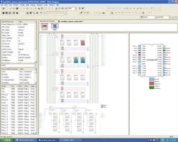
The PSoC input pin interrupt (the GPIO interrupt) supports neither state machines nor up/down counters. Instead, using the pin interrupt for the optical decoder, the two channels of optical encoder pulses A and B are connected to two inputs of the port_0, here port_0(3) and port_0(5) (Fig. 2). For pulse decoding and sensing the direction of rotation and position of the motor, the “PSoCGPIO” interrupt is enabled.
The main advantage in this design is that when an interrupt occurs, the interrupt service routine (ISR) checks if it is due to clockwise rotation of motor movement (an incremented count) or counterclockwise rotation (a decremented count).
The GPIO ISR automatically determines the direction of the motor by incrementing and decrementing the counter to measure the rotor’s direction and the motor’s position. It decodes the quadrature signals through a simple software implementation in the PSoC designer tool without using any additional hardware, as the required tasks can be implemented easily within the PSoC and its architecture.
The GPIO interrupt service routine senses input pulses A and B going low and high, and high and low (see the code listing). Correspondingly, it increments the position with Position++ operator (B-high; A-low) or decrements the position with Position–– operator (A-high; B-low).
Thus, the GPIO interrupt handler registers the position and direction of the motor movement in a single interrupt sensing. The interrupt handler takes care of the exact position of the motor movement in both directions by updating a single data pointer “Position,” incrementing the count in case of upward direction or decrementing the count while the motor moves down.
For a PC-compatible readout, a UART comprising TxD (Port_0_1) and RxD (Port_0_0) blocks is placed in the DCB12 and DCB13 digital blocks. The current “Position” data obtained through the interrupt handler is transmitted to the PC through UART blocks via the “Send Data” command. For the required baud-rate clock division, an 8-bit counter is placed in a DCB03 digital block. In this application, the UART rate is fixed at 115,200 baud.
No power supply is required for this design, since the PSoC CY8C29466 board gets its 5-V source via the USB port. The code listing provides the PSoC Editor program, including the GPIO ISR routine and UART protocol, which interfaces with the PC serial port.
J. Nandhini and J. Janani are sisters in the third year of electronics and communication engineering at Sathyabamam University, Chennai, Tamil Nadu, India. Their area of interest is embedded designs.


