This article is part of the Ideas for Design Series: Vol. 3, No. 4
Starting with Windows 7, the Windows Sensor and Location platform has become a key element of the most recent generations of this widely used operating system. It enables both the computer itself and the different applications that it uses to adapt to their current environment. Using location sensors (such as GPS receivers), the computing hardware can determine exactly where it is situated, enabling it to provide access to relevant content and functionality.
This file type includes high resolution graphics and schematics when applicable.
Related Articles
- Adding A GPS Chipset To Your Next Design Is Easy
- Dual-Mode GPS Positioning Module Achieves Sub-Meter Precision
- USB 2.0 Module Offers GPS Capability
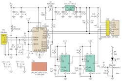
The schematic provides a GPS dongle that can be attached to such a device (running on the Windows operating system) so various location-based services can be implemented (Fig. 1). It shows how a USB bridge chip like FTDI Chip’s FT230XQ USB-to-UART can be connected to a GPS receiver to create a USB-based GPS sensor. Here, it is for a GP-2106 small form-factor GPS module with a built-in antenna.
The FT230XQ supports USB 2.0 Full Speed operation, handling data rates of 3 Mbits/s. The FT230XQ handles the USB protocol, so no USB-specific firmware programming is required. The GP-2106 delivers 48-channel operation and draws minimal power. It provides location data to the system in NMEA0183 v.3.01 format.
The implementation is straightforward. The GP-2106 module (M1) delivers the data through which positioning can be determined, while the FT230XQ (U1) carries out the UART to USB conversion. The TXD output from the FT230XQ is connected to the RXD input of the GP-2106 GPS receiver. The RXD input of the FT230XQ is connected to the TXD output from the GP-2106. These connections form a robust and reliable data link between the GPS receiver of the dongle and USB port of the computing system. The RTS# and CTS# pins of the FT230XQ are connected to disable hardware flow control.
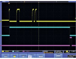
To properly start-up the GPS receiver, power must be applied and an ON pulse must be generated at pin 4 of the receiver. To satisfy this condition, two monostable multi-vibrators (74LVC1G123) are used. The first multivibrator, U2, generates a delay during which the FT230XQ is enumerated by the USB host controller and power is applied to the GPS receiver. The second multi-vibrator, U3, generates the ON pulse that starts up the chipset inside the GPS receiver module (Fig. 2).
The PWREN# pin toggles during the USB enumeration process. Then it remains low as long as U1 is enumerated and the host computer does not enter into sleep mode (meaning it is not in a state of hibernation). A logic-low level at this pin also enables the Q1 MOSFET transistor to conduct, feeding the VBUS voltage (+5 V) to the input of voltage regulator IC (U4), which steps this voltage to the 1.8 V required by the GPS receiver.
U2 triggers as soon as the PWREN# pin goes low for the first time, driving its output high. Approximately 1.6 seconds later, U2’s output will go low. This triggers U3, which will generate an ON pulse at the ON/OFF input of the GPS receiver. The GPS dongle printed-circuit board (PCB) has been equipped with the blue status LED (LED1). This LED will blink once a second when a GPS fix is available (valid position has been acquired). The 1-pulse-per-second (PPS) output from the GPS receiver through the Q2 MOSFET transistor controls LED1.
To use this FT230XQ-based GPS dongle as a location sensor, a special driver needs to be installed. Many location sensor drivers are freely available on the Internet. A highly recommended one can be downloaded from TurboIRC.com.
Read more articles in the Ideas for Design Series: Vol. 3, No. 4
Lee Chee Ee is engineering manager at FTDI Chip. Based in Singapore, he oversees all the company’s new product developments. He previously served as engineering director at ST-Ericsson. Before that, he was employed by ST-NXP Wireless and Philips Semiconductor.


