Consumer reliance on portable electronics in today’s on-the-go society continues to push the industry to come up with devices that are easier to carry, more lightweight, and deliver levels of functionality that was once the sole province of personal computers. Laptop usage is on the decline as tablets incorporate more functionality and features into their systems. Tablets are light, easy to transport and carry, and their applications-based architecture makes them very easy to use. Thanks to the latest advances in technology and processors, tablets now deliver the same performance as laptops.
As tablets continue to grow in their popularity, so does the demand for higher performance and longer battery life. This poses an interesting challenge to designers. Higher performance means increased demands on the battery. As a result, processors, chipsets, and all electronic components must be optimized to attain the highest efficiency possible to deliver the battery life desired by consumers.
This file type includes high resolution graphics and schematics when applicable.
While electronics have been improving dramatically in both form factor and performance capability, battery technology has lagged behind. The tablet printed-circuit-board (PCB) space is very limited, with the device battery taking up most of the available form factor. Research is currently underway looking for new ways to reduce the overall battery size while maintaining the same capacity. Though progress is being made, many of the advances are not yet ready for commercial use. Thus, the need for high-performance portable devices relies on the development of high-efficiency system architectures.
System Architecture
A tablet’s system architecture differs from that of the traditional personal computer. With tight form-factor and board-space restrictions, the core chipset has been redesigned and heavily integrated. Through a combination of software and integrated chipsets, the tablet system architecture can achieve performance that rivals personal computers in technology that fits into the palm of your hand.
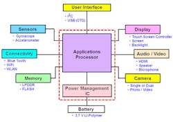
One example of a tablet system architecture features two main chips—the applications processor and the power-management IC (PMIC) (Fig. 1). Traditional personal computers have separate chipsets on the motherboard for the memory, CPU, GPU, hard drives, and other peripheral hardware. The applications processor incorporates these function blocks into one chip, and is designed to interface with every subsystem. This high level of integration substantially reduces the chip count and frees up board space.
The applications processor and PMIC work hand-in-hand to monitor, adjust, and operate the system. The applications processor uses ARM architecture, providing flexibility in customizing the configuration on a platform-by-platform basis. The RISC-based structure simplifies the system, requiring fewer components and processors than the traditional personal computer. User interfaces include I2C and USB On-The-Go (USB OTG). Chips operate at lower voltage rails to reduce some of the power loss in the system.
The PMIC is responsible for monitoring the system, making power-management decisions, and interfacing with the applications processor. It charges the battery, contains the circuitry needed to set up various voltage rails, and provides overvoltage and overcurrent protection. While the PMIC often integrates the MOSFETs used to set the voltage rails, external MOSFETs are frequently used for the reverse-voltage protection, reverse-current protection, and battery switch.
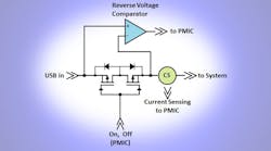
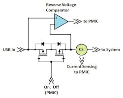
Reverse-voltage and reverse-current protection are critical to the health of the system. Traditionally, back-to-back MOSFETs are used in line with the system’s main voltage rail (e.g., the USB input) for reverse-voltage, overcurrent and reverse-current protection. Incorporating MOSFETs provides two advantages: a very low conduction loss and minimal voltage drop when the MOSFETs are on, and the blocking function of the intrinsic body diode when the MOSFETs are off.
Connecting the MOSFETs in a back-to-back configuration provides current blocking from both directions when the MOSFETs are off. The PMIC monitors the voltage and current (Fig. 2), and turns off the MOSFETs when necessary to protect the system. While many of the circuits are integrated into the PMIC, the back-to-back MOSFETs are often external components due to required voltage or current capability.
An external battery switch is used to connect and disconnect the battery from the rest of the system. The battery switch is typically a PMOS small-signal device designed to operate on low-voltage rails, providing low RDS(on) to minimize conduction losses and the voltage drop across the switch. The switch remains on when the battery powers the system, and disconnects when the device is connected to an external supply. The internal body diode of the PMOS device prevents the battery from discharging into the circuit when the switch is off (leakage current). An external battery switch is often needed due to the higher current requirements of the system.
For both the back-to-back MOSFETs and the battery-switch MOSFET, RDS(on) and footprint are of high priority in order to maximize system efficiency and minimize board space usage. Examples include ON Semiconductor’s low-RDS(on) protection MOSFETs and battery switch MOSFETs in 2- by 2- by 2-mm and 1.6- by 1.6-mm packages, such as the NTLUD3A50PZ, NTLUS3C13PZ, and NTLUS3C18PZ.
Power Management
As tablet popularity soars, so does the demand for higher performance and longer battery life. Without critical power-management techniques, though, battery life will reduce substantially. To maximize performance as well as battery life, chip designers work to optimize every aspect of the tablet’s design. This includes optimization of processor silicon, electrical components, and the system control architecture itself. Limitations to battery form factor require creative power-management schemes to maximize efficiency:
• Dynamic voltage and frequency scaling (DVFS): Software adjusts the voltage and frequency to the smallest value that’s required to finish each processor task on time, thus reducing overall energy consumption during each task.
• Load balancing between processor cores: When full processing capability isn’t needed, the applications processor turns off unused sections of the processor and balances the loads to maximize performance from underutilized cores. For example, if Core 1 is running the majority of the processes and Core 2 is running, the load-balancing technique moves any processes from Core 2 to Core 1 so that Core 2 can be powered down. Shutting down unused voltage rails and processor cores until needed ultimately delivers substantial power savings.
• Turning off idle/unused sections of the processor: Applications-processor silicon is divided into multiple sections, each with the ability to be separately turned on and off while the main power continues to be supplied to the system. Such silicon partitioning provides the means to power down non-critical sections until there’s a demand. Multicore processors will keep the additional cores in sleep mode or powered down until needed.
• Separating the VCORE and logic voltage rails: Voltage rails are separate within the applications processor itself, making it possible to power down unused voltage rails and circuits until they’re needed.
In addition to these power-management techniques, individual components implement power savings in various ways. For example, components may be of the high-performance variety. Memory can be low power and contain built-in power management. Or level shifters can be used to scale the voltage rails up and down. Furthermore, investigation into battery-chemistry variations is underway with an eye toward maximizing battery capacity.
Tablet Future
As tablets gain momentum, consumers desire larger screens, more performance, and thinner or lighter form factors. To meet those demands, designers are looking into new battery chemistries and increasing the number of cells in tablets, among other solutions.
This file type includes high resolution graphics and schematics when applicable.
With the burgeoning demands and rising popularity in the smartphone space, more consumers are looking to low-cost tablets. The tablet market has split into the low-end and the high-end sectors. High-end tablets have integrated functionality into a streamlined chipset, and tend to use quad-core processors. Low-end tablets implement a more discrete solution with a larger chipset. Overall, the expanding tablet market opens the door to many opportunities for chip manufacturers of integrated and discrete components alike.
Ann Starks, senior applications engineer at ON Semiconductor, joined the power MOSFET division in 2008, focusing on high-performance power conversion and power management for the computing, wireless, and portables markets.
ON Semiconductor offers energy-efficient power and signal management, logic, discrete, and custom solutions to help customers solve their unique design challenges in automotive, communications, computing, consumer, industrial, LED lighting, medical, military/aerospace and power supply applications.


