Making SOSA-Aligned System Development More Versatile
The Open Group’s Sensor Open Standards Architecture (SOSA) Consortium was started to provide more commonality across platforms for the tri-service community. Part of the effort is to bring together previously disparate efforts such as HOST, CMOSS, VICTORY, etc., into more compatible forms. The benefits to the military are the comparable ease of integration, less training time, a more plug-and-play ecosystem, less confusion, less vendor lock, lower costs, and more.
A key aspect of the SOSA effort is to support a more manageable subset of module configurations for rugged computing systems. By (currently) only limiting the slot profile options and not defining backplane profiles, the goals above are achieved without over-restricting options.
The backplane may still have customization as it needs to support many options for design speeds, I/O requirements, slot profile combinations, RP/optical contacts, and more. After all, there’s comparatively low cost, low risk, and shorter development time to customize a backplane than a single-board computer (SBC) or other plug-in card (PIC). Does this mean a custom backplane or chassis needs to be designed from scratch for every configuration—even for a development system? Not necessarily.
Background on Backplanes for SOSA Slot Profiles
A “Backplane for SOSA Slot Profiles” is a mouthful, but it’s more accurate than “SOSA Aligned Backplane,” as the specification doesn’t define the specifics of the backplane. The specifications are largely based on 3U and 6U OpenVPX as defined in VITA 46/48, VITA 65/66/67, and other related standards.
VITA 65, for example, offered a wide range of module, slot, and backplane profiles along with the details as to how these modules and backplanes are interconnected (including pinout maps, routing diagrams, etc.). SOSA greatly reduced the module profiles that can be used in the specification to simplify things (which incorporate the benefits listed earlier).
From a chassis platform perspective, SOSA’s efforts are driving the backplane speed requirements, more advanced cooling solutions for hotter plug-in cards, simpler power-supply options, RF and fiber interfaces that lead to new I/O solutions, and chassis management.
Another element of the SOSA initiative is to maximize performance. For the backplane/chassis supplier, this means faster speeds across the backplane and more advanced cooling requirements.
A few years back, PCIe Gen3 speeds (8 Gbaud/s) across the backplane were commonplace and 40 GbE (4x lanes of ~ 10 Gbaud/s) was the higher speed exception. With SOSA, 40 GbE is often the lower speed option with PCIe Gen4 (16 Gbaud/s) and 100 GbE (4x lanes of ~ 25 Gbaud/s) as the norm.
The next section talks about upcoming higher bandwidth efforts. These speeds require advanced routing techniques, high-grade PCB material that’s more expensive, higher-speed connector options of the VPX connector, back-drilling of vias, and more. The routing challenges are exacerbated by the optical and RF connector module that may be installed in the backplane, particularly when the P2 connector (and that routing space) is consumed in a 3U OpenVPX backplane with these connectors.
Development Backplanes for SOSA-Aligned OpenVPX Systems
The most obvious approach to having a development system for a SOSA-aligned design is a power and ground only backplane (although the utility plane that includes the SMbus is usually routed as well). All other signals are pass-through only (unrouted). This allows for the use of any SOSA-aligned PIC to be powered up, and with Meritec cabling on the RTM (rear) connectors, it can be routed to 25-Gbaud/s speeds.
But this approach doesn’t mean that only development backplanes need to be created to start testing out boards for your new system. On the contrary, many elements are in play, whether it’s a development backplane or a deployable unit. These include:
- Number of slots and spacing requirements
- 3U or 6U height, hybrids
- Combination of slot profiles
- RF/optical interfaces that are utilized, if any
- VPX connector options (related to speeds)
- Backplane speed requirements across data plane, control plane, and expansion plane
In a power and ground only backplane, the speeds don’t fully come into play because there’s no routing. However, to test 100-GbE cards, it’s recommended to use the RT3 version of the MULTIGIG connector. That connector has a different footprint than the RT2 (intermateable, but not intermountable), so a different PCB is required.
Furthermore, higher-speed connector options are available, such as VITA 91, which provides a high-density connector for speeds up to 56 Gb/s. So, in that respect the speed requirement for the backplane should be considered.
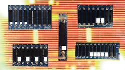
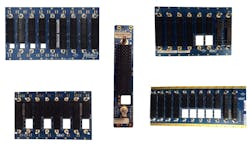
From there, a wide range of RF/optical cutouts may need to be employed to offer options for VITA 67.3c, VITA 67.3d, or other styles that both SOSA and other OpenVPX applications may utilize. This can be a wide array. The backplane manufacturer has to offer multiple styles of backplanes, just for the simple testing and development of PICs. Figure 1 shows a few power and ground only backplane examples, some of which have RT2 connectors and others with RT3 connectors.
Development backplanes can be connected in a chassis to expand configuration options. For example, a single-slot backplane can be connected to a routed backplane to add an RF/optical slot option. Or, two power and ground backplanes may be combined to configure the right array of optical/RF interfaces along with VPX slots. Pixus has devised cabling techniques to route both power and the SMBus across multiple backplanes inside a development chassis. This enables the multiple backplanes to act as one in the system.
VITA 91 and Upcoming High-Performance Options
While a power and ground backplane is a highly versatile approach for test and development of a new SOSA-aligned OpenVPX system, oftentimes a customer will want a routed backplane for prototyping. As shown earlier, a significant number of options exist for SOSA-aligned slot profile combinations.
That said, patterns do emerge to the groupings of I/O-intensive, compute, and switch modules that design engineers want to include in their system. There are ways to leverage fully routed backplanes for prototyping/testing as well.
We’ve shown that a wide range of power and ground and routed backplanes are available to start your SOSA-aligned or 3U OpenVPX system development. But as we mentioned, there’s a constant drive in VITA and SOSA for higher performance—the desire is to go beyond the speed limitation of the MULTIGIG RT3, which again supports ~ 25-Gbaud/s speeds for 100-GbE performance.
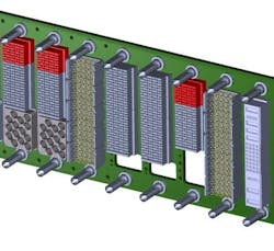
Designs on the cutting edge now utilize new higher-speed and -density connectors. For example, Figure 2 shows a 6+1 slot, 3U OpenVPX SOSA-aligned backplane with two slots supporting VITA 91 high-density connectors at up to 56-Gb/s speeds.
Another future push is for VITA 100 and other efforts to drive the signal performance even higher. This effort is still in draft in VITA (as of this writing), but the connector will aim to double the pin count via increased density and achieve 128-Gb/s speeds, as well as support PCIe Gen6/Gen7. For many of the next generation of chipsets offering this massive performance, the 3U size may not provide enough real estate.
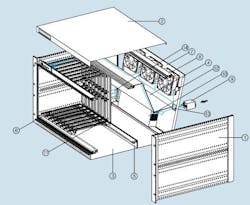
The other standard option of 6U is a bit large for many applications. So, we may see the evolution of a 4U PIC form factor. While the size is unusual, with a modular design platform, it can be accomplished without starting from scratch. See Figure 3 for exploded view of a PixCool chassis that allows for a wide range of chassis heights, depths, widths, etc.
Advanced Cooling Testing and Chassis Management
Efforts are underway for Air Flow By and Air Flow Through, which utilize air flowing over the module or through the module, respectively. A test system for Air Flow Through has been challenging as the VITA 48.8 specification requires special gasketing that’s typically cost-prohibitive for a development system.
Specialty solutions have been developed, but a standard test chassis remains elusive (see Figure 4 for a MIL rugged enclosure design that leverages the VITA 48.8 Air Flow Through approach). However, there are efforts in VITA 48.5, VITA 48.9, and related specifications that aim to simplify the board/module interface to avoid the expensive gasketing.
Another element of testing a SOSA-aligned system is the chassis manager. Current mezzanine-based approaches are available where the chassis manager affixes to the rear of the backplane so that a slot isn’t consumed. However, a simpler approach can be utilized for testing. Using a small development kit, a VITA or SOSA-aligned chassis manager can be placed inside any test chassis with simple cabling to the backplane. This allows for the full testing of the SMbus signals, KX port, Base-T port, power and fans signals, and the rest of the chassis-manager pinout.
Pulling It All Together for Test and Development
While any one aspect of an advanced SOSA-aligned (or other MOSA) design can be challenging, it’s important to balance the various factors such as chassis configuration, backplane details, I/O requirements, backplane performance, chassis management, and more. With a modular design approach and multiple enclosure types, a chassis provider is able to facilitate virtually limitless configurations.
The multiple power and ground and routed backplanes that support SOSA-aligned slot profiles can be creatively interconnected in a system to meet a wide range of requirements, while limiting or completely avoiding customization.
>>Check out other content from our Rugged Systems Design Week
About the Author

Justin Moll
Vice President of Sales & Marketing, Pixus Technologies
Justin Moll is the Vice President of Sales & Marketing for Pixus Technologies and has been with the company since 2012. He’s active in trade associations such as VITA and PICMG and served as the Vice President of Marketing for PICMG. Justin has been a keynote speaker and featured commentator at multiple embedded computing industry events.
