Adding capacitive sensing to a consumer or industrial product can be a daunting challenge that requires developers to maintain sensor robustness and responsiveness while minimizing current consumption and addressing other system-level design priorities. Navigating this embedded development process without the help of tools and support can lead to lengthy trial-and-error design iterations, both in software and hardware, resulting in slipped release schedules and suboptimal solutions.
While fixed-function capacitive-sensing solutions can ease some of these design burdens, those devices are rarely pure drop-in solutions, as many still rely on developer-side configuration and calibration. In addition, fixed-function solutions prevent developers from giving the sensor additional responsibilities in a system, which can help reduce system current consumption, board size, and bill-of-materials (BOM) cost.
This file type includes high resolution graphics and schematics when applicable.
Capacitive-sensing solutions based on general-purpose 8-bit microcontrollers (MCUs) can help designers through each step of the development process, enabling them to generate projects using capacitive-sensing firmware libraries, add and debug features with an intuitive and powerful integrated development environment (IDE), and view real-time capacitive-sensing performance in-system using capacitive-sensing visualization tools.
Capacitive-Sensing Design Basics
Capacitive-sensing technologies measure the capacitance of an electrode connected to the sensor’s input. The electrode being measured is often a printed-circuit-board (PCB)-designed round pattern of solid copper about 10 mm in diameter that’s isolated from the board’s ground. A thin overlay, usually made of a type of plastic or glass, is sometimes adhered to the PCB, and the resulting system can function as a touch interface that doesn’t require mechanical buttons.
When a user touches the area of the overlay covering the electrode, the capacitance of the human body affects the capacitive coupling of the electrode, resulting in a change in the on-chip capacitive sensor’s measured capacitance. Post-sample processing on the stream of samples will detect this change in capacitance and qualify it as a “touch.”
A common goal among all capacitive-sensing technologies is the ability to sense a relatively small change in an analog signal while operating in a mixed-signal system that has the potential to be electrically noisy. As a result, designing a robust and reliable sensing interface can be challenging.
In addition to hardware considerations regarding board layout and electrode design, the sensor’s post-sample processing operations must update state variables while responding dynamically to system-level events. Touch-sensing strategies usually involve maintaining a baseline, which is the expected output of the capacitive sensor when the electrode is in an untouched state, as well as setting one or more touch thresholds relative to that baseline. Processing compares these thresholds against sensor output to determine the occurrence of touch and release events. In addition to these operations, the firmware must be designed to operate as efficiently as possible to minimize both code size and average current draw.
To help ease the burden of firmware development, many capacitive-sensor vendors offer fixed-function devices, which provide an integrated circuit that samples capacitance and outputs touch qualification through either a serial interface or port-pin logic states. While these products may appear attractive to developers because of their ease of use, the lack of programmable flash and limited customizable feature sets can force system developers to place more responsibilities for touch qualification onto more power-hungry host processors.
For example, a fixed-function device (FFD) that becomes susceptible to false-positive touch events in high-interference environments could force a host processor to ignore touch-qualification information from the FFD and instead read the FFD’s raw data and develop its own touch-qualification algorithms. Similarly, an FFD erroneously sending frequent touch-event signals to a host processor will cause that processor to wake from its lower power state to examine touch events, driving up average current draw for a system.
A capacitive-sense-enabled microcontroller, such as the EFM8SB1 8-bit MCU from Silicon Labs, when used with a capacitive-sensing firmware library, combines a fixed-function device’s ease of use with the flexibility of a general-purpose mixed-signal MCU. The precompiled library provides touch-qualification algorithms, state variable maintenance, and a simple application programming interface (API) for retrieving touch-event information. The remaining flash memory and numerous on-chip peripherals give developers the opportunity to add more features and responsibilities to the MCU.
A cap-sense firmware library for an 8-bit MCU leverages the device’s power management unit (PMU) and on-chip real-time clock. This allows the developer to create a sophisticated, mode-switching MCU that can achieve less than 1 µA average current draw in most use cases.
Simplify Cap-Sense Design with an IDE
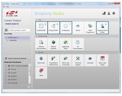
An IDE, such as Silicon Labs’ Simplicity Studio platform, provides end-to-end development support for capacitive-sensing-enabled embedded-system designs. This ranges from configuring and importing the capacitive-sensing firmware library, to in-system debugging and real-time visualization of capacitive-sensing output. Many IDEs provide a launcher window that dynamically populates tiles depending on the MCU being used in development. It will show the tools offered to support every step of development.
The annotations on the launcher (Fig. 1) show the basic development path followed by most users:
• Configurator generates the capacitive-sensing library and allows developers to configure hardware peripherals.
• The IDE provides a code development and debug environment where additional features can be added to a firmware project.
• An energy profiler tool built into the IDE provides real-time current-draw measurements of a project that’s been downloaded to a starter-kit evaluation board.
• A capacitive-sense profiler tool displays runtime capacitive-sensing data raw values and algorithm-derived values such as touch state, baselines, and thresholds.
Configuring Capacitive-Sensing Projects
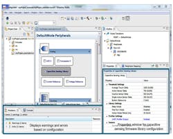
A project’s development starts with the configurator tool (Fig. 2), which provides users with a graphical interface and properties windows. In this tool, customers can designate port pins as capacitive-sensing inputs and configure library performance settings (e.g., scan period, low-power functionality). If a customer’s configuration choices require implementation of other configuration settings, a “problems perspective” view lists the relevant warnings and errors. These items can be clicked on to jump to specific settings that must be changed.
As the user configures the project, appropriate files are generated and organized in a project explorer window. Clicking on one of these files will cause the configurator perspective to switch to the IDE perspective. Users can go back to the configurator and make changes or additions to a configuration anytime by clicking on the configurator file, which is also listed in the project explorer window.
Code Development and Download in the IDE
A comprehensive Eclipse-based IDE offers all of the features that developers expect in a development environment, including code completion and formatting tools. The IDE can provide deep integration with the debug circuit on evaluation boards as well as USB debug adapters, enabling full read/write access to MCU registers and variables.
When developers include the capacitive-sensing firmware library in their projects, the configurator provides a build-ready project that will scan enabled sensors, qualify touches, and even output information through the serial interface. This feature lets customers generate a project without any additional development in the IDE. In other words, if a user wants to test out capacitive sensing on a board, the IDE can simply be used to build and download the image, without any coding required.
Characterizing Performance with Profilers
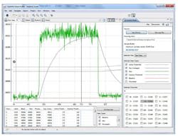
Once code has been downloaded to the 8-bit MCU, the developer can use the IDE’s energy profiler and capacitive-sense profiler to see how configuration choices made in the configurator and any additional features created in the IDE affect current consumption and capacitive-sensing performance. For capacitive-sensing applications, the capacitive-sense profiler (Fig. 3) is particularly useful, because users are able to examine performance in-system, complete with product overlays and other late-stage-development system components in place.
The profiler supports advanced features, such as standard deviation and signal-to-noise-ratio calculations, to characterize board performance. The tool also allows the captured data to be exported into a text file for further examination in other programs like Microsoft Excel.
Development Workflow Flexibility
One of the challenges in designing capacitive-sensing systems concerns managing a project through an iterative development process—build a project, test performance, and return to development to further optimize performance. The tools included in Silicon Labs’ Simplicity Studio platform are designed to support these kinds of workflow cycles.
For example, a developer might create a capacitive-sensing project designed for thinner 1/16-in. overlays, build the project, and test performance in the IDE’s capacitive-sense profiler. If the product’s requirements change, modifying the overlay’s thickness to 1/8 in., the developer only needs to click on the configurator file for that project and adjust the touch-threshold settings. After making that change, the developer just needs to rebuild and download the project, and performance with the thicker overlay can be seen in real-time through Profiler.
Adding other firmware features to a project as it develops provides another example of iterative development. Let’s say that a developer has created a project with capacitive sensing, and checked that all performance and current-consumption requirements for the project are met using the IDE’s diagnostic tools. The developer then starts work on a serial interface that controls other system components based on capacitive-sensing input. This new component could impose new requirements on current draw and capacitive-sensing responsiveness.
With Simplicity Studio, for example, the new component can be added to the project’s code base without breaking the link between the source code and the configurator tool. Once the project is built, the developer might find that the functionality of the new component requires a modification to the capacitive-sensing component.
For example, the system might need to stay in an active mode and scan for button touches for a longer period of time than was first configured, because the serial interface to the rest of the system must stay active and optimally responsive to input. The developer can go to the configurator, adjust the amount of time the system stays awake before entering a low-power sleep state between touch sessions, and then rebuild code.
Key-Sequence Example
The ability to generate code and minimize the amount of low-level capacitive sensing code that needs to be written leads to many use cases that may add application-specific sensing features to the sensing MCU. These use cases distinguish general-purpose MCU solutions that support capacitive-touch capabilities from fixed-function solutions in which all application-specific functionality must be added to more power-hungry processors in the system. A key-sequence detector feature clearly illustrates the benefits of using a general-purpose MCU in capacitive sensing.
In many products with control panels, the end user must enter a key sequence or password to unlock product functionality. In a system that uses a fixed-function device, the main processor would have to wake up upon the first keystroke, wait in an active state while the user enters the key sequence, and then process the sequence to determine if it matches the correct password. This might not seem like a significant amount of time for a high-performance MCU to be active, but let’s examine the total power budget.
Say, for instance, that this battery-powered control panel sees an average of 100 15-second user interaction sessions per day. The sessions have two phases: a validation phase where the key sequence is entered and checked against a password; and a response phase in which the control panel issues commands elsewhere in the system. In a design with a fixed-function device, the main processor must be awake for both the validation and response phase, which in this example is 15 seconds per session.
If an 8-bit microcontroller, such as the EFM8SB1 MCU, is used for the validation phase, the main processor only needs to be awake for the response phase, or about 7.5 seconds. Let’s also say that the main processor uses 10 mA when active, a common trait of many 32-bit processors, and the 8-bit MCU would use 20 µA when active, which is achievable thanks to the sophisticated power -management state machine in the capacitive-sensing firmware library. In this example, we’re simplifying the current draw a bit and not considering the current used between user interaction sessions.
This file type includes high resolution graphics and schematics when applicable.
In situations where an FFD requires that the main processor be active during validation, the system’s average current draw would be about 17 µA. If the lower-power 8-bit MCU is used for part of the interaction session, the average current draw would be about 9 µA. If this battery-powered system were running on a coin-cell battery, such as a CR2032 with a typical capacity of around 225 mAh, an 8-bit design based on an EFM8SB1 MCU would run without a battery change for almost three years. The system with an FFD would require a battery change in about 1.5 years—a significant reduction in run time that could mean the difference between a well-received product and a frustrating product destined for one-star Amazon reviews.
Smart Design Leads to Better Products
No two product designs will have the same requirements or end-customer use cases. For this reason, using a “one size fits all” fixed-function device is unlikely to yield a design that manages responsibilities in coordination with other system ICs to optimize functionality with minimal current draw. Using a general-purpose 8-bit microcontroller running a capacitive-sensing firmware library, along with tight integration with optimized development tools, makes it possible for developers to find smart ways of incorporating capacitive sensing into their designs while balancing other goals and priorities.


