Power Management Chapter 9: Battery-Power Management ICs
This articles is part of the Power Management Series in the Power Management section of our Series Library.
Download this article as a .PDF eBook.
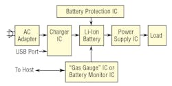
Use of battery-powered systems have expanded as consumers have migrated to portable phones, MP3 players, digital cameras, and more. One reason for this growth has been the availability of batteries and power-management ICs that provide the required support for increasingly complex electronic systems. Fig. 9-1 shows the basic power-management subsystem employed in a battery-based system.
To be effective, these power-management subsystems must:
- Minimize battery size and weight while maximizing available run time.
- Provide the appropriate regulated output voltage over the specified input voltage range and load current.
- Minimize overall space and weight for associated components.
- Minimize heat dissipation to eliminate the need for sophisticated thermal management that adds size, weight, and cost.
- Allow a circuit-board layout that minimizes EMI.
- Maximize system reliability.
9-1. A typical battery-based power-management subsystem consists of single or multiple-function ICs.
Battery Selection
To meet these design objectives, the power-management subsystem design begins with the battery, which may be a non-rechargeable primary battery or a rechargeable secondary battery. Primary battery examples are alkaline and lithium metal cells. Popular rechargeable batteries are nickel cadmium (NiCd), nickel-metal hydride (NiMH), lithium-ion (Li-ion), and lithium-polymer (Li-pol).
Lithium-ion batteries have the greatest electrochemical potential and the highest energy density per weight. The Li-ion battery is safe, provided certain precautions are met when charging and discharging. Li-ion energy density is about twice that of the standard NiCd. Besides high capacity, the load characteristics are reasonably good and behave similarly to the NiCd in terms of discharge characteristics. Its relatively high cell voltage (2.7V to 4.2V) allows one-cell battery packs.
Exercise caution when handling and testing Li-ion batteries. Do not short-circuit, overcharge, crush, drop, mutilate, penetrate, apply reverse polarity, expose to high temperature, or disassemble. Use the Li-ion battery with its designated protection circuit.
The Li-pol battery differs from the Li-ion type in its fabrication, ruggedness, safety, and thin-profile geometry. Unlike the Li-ion, the Li-pol has minimal danger of flammability because it does not use a liquid or gelled electrolyte like the Li-ion. The Li-pol has simpler packaging and a lower profile than the conventional Li-ion battery.
Battery-Charger ICs
Battery chemistries have unique requirements for their charge technique, which is critical for maximizing capacity, cycle life, and safety. Linear topology works well in applications with low-power (e.g., one- or two-cell Li-ion) battery packs that are charged at less than 1A. However, switch-mode topology is better suited for large (e.g., three or four series Li-Ion or multiple NiCd/NiMH) battery packs that require charge rates of 1A and above. Switch-mode topology is more efficient and minimizes heat generation during charging, but can produce EMI if not packaged properly.
The charge and discharge capacity of a secondary battery is in terms of “C,” given as ampere-hours (Ah). The actual battery capacity depends on the C-rate and temperature. Most portable batteries are rated at 1C. A discharge of 1C draws a current equal to the rated capacity, that is, a battery rated at 1000mAh provides 1000mA for one hour if discharged at 1C rate.
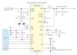
9-2. Texas Instruments’ Bq24259 is a switch-mode battery-charge management and system power-path management IC for one-cell Li-ion and Li-polymer batteries.
Li-ion batteries have a higher voltage per cell, tighter voltage tolerance, and the absence of trickle or float charge when reaching full charge. Charge time for Li-ion batteries charged at a 1C initial current is about three hours. Full charge occurs after reaching the upper voltage threshold and the current drops and levels off at about 3% of the nominal charge current. Increasing Li-ion charge current has little effect on shortening the charge time. Although it reaches the voltage peak faster with higher current, the topping charge will take longer. Li-ion batteries cannot absorb overcharge, which can cause the cell to overheat. Li-ion constant-current- constant-voltage (CCCV) chargers are important to get the maximum energy into the battery, without overvoltage.
Performance and longevity of rechargeable batteries depends on the quality of the charger IC. One type of charger IC (used only for NiCd) applies a fixed charge rate of about 0.1C (one tenth of the rated capacity). A faster charger takes three to six hours with a charge rate of about 0.3C.
A charger for NiMH batteries could also accommodate NiCds, but not vice versa because a NiCd charger could overcharge a NiMH battery. Lithium-based chargers require tighter charge algorithms and voltages. Avoid a charge rate over 1C for lithium battery packs because high currents can induce lithium plating. With most lithium packs, a charge above 1C is not possible because the protection circuit limits the amount of current the battery can accept.
Bq24259
The bq24259 from Texas Instruments is a switch-mode battery charge-management and system-power-path management device for a one-cell Li-Ion and Li-polymer battery (Fig. 9-2). Its low-impedance power path optimizes switch-mode operation efficiency, reduces battery charging time, and extends battery life during discharging phase.
The IC supports 3.9 V to 6.2 V USB input sources, including a standard USB host port and USB charging port with 6.4 V overvoltage protection. It also supports USB 2.0 and USB 3.0 power specifications with input current and voltage regulation.
The power-path management regulates the system slightly above battery voltage, but does not drop below 3.5 V minimum system voltage (programmable). With this feature, the system keeps operating even when the battery is completely depleted or removed. When the input source current or voltage limit is reached, the power-path management automatically reduces the charge current to zero and then discharges the battery until the system power requirement is met. This supplement-mode operation keeps the input source from getting overloaded.
The IC initiates and completes a charging cycle when host control is not available. It automatically charges the battery in three phases:
- Pre-conditioning
- Constant current
- Constant voltage
In the end, the charger automatically terminates when the charge current is below a preset limit in the constant voltage phase. Later on, when the battery voltage falls below the recharge threshold, the charger will automatically start another charging cycle.
Safety features for battery charging and system operation include:
- Negative thermistor monitoring
- Charging safety timer
- Overvoltage protection
- Overcurrent protection
The thermal regulation reduces charge current when the junction temperature exceeds 120°C (programmable). An output reports the charging status and any fault conditions. And the IC immediately notifies host when fault occurs.
MAX8900
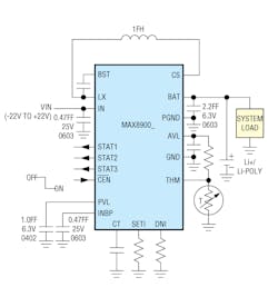
Maxim Integrated’s MAX8900 is a high-frequency switch-mode charger for a 1-cell Li+ or Li-Poly battery (Fig. 9-3). It delivers up to 1.2A to the battery from 3.4V to 6.3V (MAX8900A/MAX8900C) or 3.4V to 8.7V (MAX8900B).The 3.25MHz switch-mode charger is ideally suited to small portable devices such as headsets and ultra-portable media players because it minimizes component size and heat.
The MAX8900 is protected against input voltages as high as +22V and as low as -22V. Battery protection features include low-voltage prequalification, charge-fault timer, die-temperature monitoring, and battery temperature monitoring. The battery temperature monitoring adjusts the charge current and termination voltage as described in the JEITA (Japan Electronics and Information Technology Industries Association) specification for safe use of secondary Li+ batteries.
Charge parameters are adjustable with external components. An external resistance adjusts the charge current from 50mA to 1200mA. Another external resistance adjusts the prequalification and done-current thresholds from 10mA to 200mA. The done-current threshold is very accurate, achieving ±1mA at the 10mA level. The charge timer is adjustable with an external capacitor.
A proprietary hysteretic-current PWM control scheme ensures high efficiency, fast switching, and physically tiny external components. Inductor ripple current is internally set to provide 3.25MHz. At very high duty factors, when the input voltage is lowered close to the output voltage, the steady-state duty ratio does not allow 3.25MHz operation because of the minimum off-time. The controller then provides minimum off-time, peak current regulation. Similarly, when the input voltage is too high to allow 3.25MHz operation due to the minimum on-time, the controller becomes a minimum on-time, valley current regulator.
To prevent input current transients, the rate of change of the input current (di/dt) and charge current is limited. When the input is valid, the charge current ramps from 0mA to the fast-charge current value in 1.5ms. Charge current also soft-starts when transitioning from the prequalification state to the fast-charge state. There is no di/dt limiting when transitioning from the done state to the fast-charge state.
Battery-Monitor ICs
Portable systems are sensitive to usable battery life. This is particularly important for computers where a loss of power could mean a loss of stored data. Therefore, it is useful to provide a real-time indication of remaining battery life. One approach is a battery monitor that accumulates battery data and transmits it to a host processor. Another approach is a “gas gauge” that displays battery life within its associated equipment.
Battery monitors are mixed-signal ICs that include digital memory and registers that store battery data. Analog circuits include temperature sensors and amplifiers, as well as interface circuits. To measure battery current, a monitor usually includes either an internal or external current sense resistor. Voltage and current measurements are usually via an on-chip A/D converter.
9-3. Maxim’s MAX8900 is a high-frequency switch-mode charger for a one-cell Li+ or Li-polymer battery.
One solution to this battery-sensitive situation is to include a means for providing a real-time indication of remaining battery life to the system user. Battery monitors are actually data-acquisition systems that accumulate data related to battery parameters and then transmit the battery data to a host processor.
Battery monitors are mixed-signal ICs that incorporate both analog and digital circuits. These monitors include one or more types of digital memory and special registers to hold battery data. Analog circuits include temperature sensors and amplifiers, as well as some interface circuits.
To measure battery current, the monitors usually include either an internal or external current sense resistor. Voltage and current measurements are usually via an on-chip A/D converter.
Among the monitored battery parameters are overcharge (overvoltage), overdischarge (undervoltage), and excessive charge and discharge currents (overcurrent, short circuit), information of particular importance in Li-ion battery systems. In some ways a battery monitor assumes some of the functions of a protection circuit by protecting the battery from harmful overcharging and overcurrent conditions.
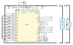
9-4. Intersil’s ISL94203 is a stand-alone battery-pack monitor that provides monitor and protection functions.
Intersil’s (now part of Renesas) ISL94203 is a stand-alone battery-pack monitor that provides monitor and protection functions without using an external microcontroller (Fig. 9-4). The IC locates the power-control FETs on the high side with a built-in charge pump for driving N-Channel FETs. The current sense resistor is also on the high side.
Power is minimized in all areas, with parts of the circuit powered down a majority of the time, to extend battery life. At the same time, its RGO output stays on, so that any connected microcontroller can remain on most of the time.
The ISL94203 includes:
- Eight-cell voltage monitors that support Li-ion CoO2, Li-ion Mn2O4 and Li-ion FePO4 chemistries
- Input level shifter to enable monitoring of battery stack voltages
- 14-bit ADC converter, with voltage readings trimmed and saved as 12-bit results
- 1.8V voltage reference (0.8% accurate)
- 2.5V regulator, with the voltage maintained during sleep
- Automatic scan of the cell voltages; overvoltage, undervoltage, and sleep voltage monitoring
- Selectable overcurrent detection settings
- 8 discharge overcurrent thresholds
- 8 charge overcurrent thresholds
- 8 short circuit thresholds
- 12-bit programmable discharge overcurrent delay time
- 12-bit programmable charge overcurrent delay time
- 12-bit programmable short-circuit delay time
- Current-sense monitor with gain that provides the ability to read the current-sense voltage
- Second external temperature sensor for use in monitoring the pack or power FET temperatures
- EEPROM for storing operating parameters and a user area for general purpose pack information
- Cell balancing uses external FETs with internal state machine or external microcontroller
Battery Gas-Gauge ICs
The gas-gauge IC is usually found within the battery pack. Because specific inputs on the gas-gauge IC connect directly to the battery, those inputs must consume very little power. Otherwise, battery life will be reduced during long storage periods. Initially, the battery must be fully charged and the counters and registers set to states consistent with a fully charged battery. As discharge occurs, the gas-gauge IC tracks the amount of charge removed from the battery.
Most battery gas gauges compensate for both temperature and charge/discharge rate. Typically, it displays the available charge on LEDs and also can send the charge data to an external processor via an I/O port. The LED presentation usually consists of five or six segments of a “thermometer” display. To conserve battery power, the display is only activated at the user’s command. At full charge, all the LED segments are lit. As battery life decreases, the gas-gauge IC extinguishes successive segments on the thermometer display.
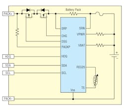
9-5. Texas Instruments’ bq27741-G1 provides fuel gauging for single-cell Li-ion battery packs.
The gas-gauge IC calculates the available charge of the battery while compensating for battery temperature because the actual available charge is reduced at lower temperatures. For example, if the gas-gauge IC indicates that the battery is 60% full at 25°C, then the IC indicates 40% full when cooled to 0°C, which is the predicted available charge at that temperature. When the temperature returns to 25°C, the displayed capacity returns to 60%. This ensures that the indicated capacity is always conservatively representative of the charge available for use under the given conditions.
Depending on the battery type, the gas-gauge IC also adjusts the available charge for the approximate internal self-discharge of the battery. It adjusts self-discharge based on the selected rate, elapsed time, battery charge level, and temperature. This adjustment provides a conservative estimate of self-discharge that occurs naturally and that is a significant source of discharge in systems that are not charged often or are stored at elevated temperatures.
The gas-gauge IC is usually packaged within the battery pack. Because specific inputs on the gas-gauge IC connect directly to the battery, those inputs must consume very little power. Otherwise, battery life will be reduced during long storage periods.
The battery gas gauge continuously compensates for both temperature and charge/discharge rate. Typically, it displays the available charge on LEDs and also can send the charge data to an external processor via an I/O port. The LED presentation usually consists of five or six segments of a “thermometer” display. To conserve battery power, the display is only activated at the user’s discretion.
Battery gas-gauge ICs employ mixed-signal, analog, and digital circuits. One technique is to use analog circuits to monitor battery current by measuring the voltage drop across a low-value resistor (typically 20mW to 100mW) in series with the battery. This provides the charge input to the battery and the charge subsequently removed from the battery. Integrated over time, the scaled voltage drives internal digital counters and registers. The counters and registers track the amount of charge available from the battery, the amount of charge removed from the battery since it was last full, and the most recent count value representing “battery full.”
Bq27741-G1
Texas Instruments’ bq27741-G1 Li-ion battery fuel gauge is a microcontroller peripheral that provides fuel gauging for single-cell Li-Ion battery packs (Fig. 9-5). The device requires little system microcontroller firmware development for accurate battery fuel gauging. The fuel gauge resides within the battery pack or on the system’s main board with an embedded battery (non-removable).
Cell information is stored in the fuel gauge in non-volatile flash memory. Many of these data flash locations are accessible during application development. They cannot, generally, be accessed directly during end-equipment operation. To access these locations, use individual commands, a sequence of data-flash-access commands.
The key to the high-accuracy gas-gauging prediction is the proprietary Impedance Track algorithm. This algorithm uses cell measurements, characteristics, and properties to create state-of-charge predictions that can achieve less than 1% error across a wide variety of operating conditions and over the lifetime of the battery.
The fuel gauge provides:
- Hardware-based overvoltage
- Hardware-based undervoltage
- Overcurrent in charge or discharge
- Short-circuit protection
Information provided includes:
- Remaining battery capacity(mAh)
- State-of-charge (%)
- Run-time to empty (minimum)
- Battery voltage (mV) and temperature (°C)
- Vital parameters recorded throughout battery lifetime
Battery-Protector ICs
An added requirement for Li-ion battery packs is a protection circuit that limits each cell’s peak voltage during charge and prevents the voltage from dropping too low on discharge. The protection circuit limits the maximum charge and discharge current and monitors the cell temperature. This protects against overvoltage, undervoltage, overcharge current, and overdischarge current in battery packs
Ideally, the protection circuit should consume no current when the battery-powered system is turned off. However, the protector always consumes some small current. A single-cell rechargeable Li+ protection IC provides electronic safety functions required for rechargeable Li+ applications including protecting the battery during charge, protection of the circuit from damage during periods of excess current flow and maximization of battery life by limiting the level of cell depletion. Protection is facilitated by electronically disconnecting the charge and discharge conduction path with switching devices such as low-cost N-channel power MOSFETs.
Battery-Protection IC
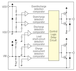
The S-8240A Series monitors the voltage of the battery connected between VDD pin and VSS pin, the voltage between VM pin and VSS pin to control charging and discharging (Fig. 9-6). When the battery voltage is in the range from overdischarge detection voltage (VDL) to overcharge detection voltage (VCU), and the VM pin voltage is in the range from charge overcurrent detection voltage (VCIOV) to discharge overcurrent detection voltage (VDIOV), the S-8240A Series turns both the charge and discharge control FETs on. This condition is called the normal status, and in this condition charging and discharging can be carried out freely.
9-6. The S-8240A Series from S.I.I. monitors the voltage of the battery connected between VDD pin and VSS pin and the voltage between VM pin and VSS pin to control charging and discharging.
The resistance between VDD pin and VM pin (RVMD), and the resistance between VM pin and VSS pin (RVMS) are not connected in the normal status.
When the battery voltage becomes higher than VCU during charging in the normal status and the condition continues for the overcharge detection delay time (tCU) or longer, the S-8240A Series turns the charge control FET off to stop charging. This condition is called the overcharge status.
The overcharge status is released in the following two cases.
1. In the case that the VM pin voltage is lower than VDIOV, the S-8240A Series releases the overcharge status when the battery voltage falls below overcharge release voltage (VCL).
2. In the case that the VM pin voltage is equal to or higher than VDIOV, the S-8240A Series releases the overcharge status when the battery voltage falls below VCU.
When the discharge is started by connecting a load after the overcharge detection, the VM pin voltage rises by the Vf voltage of the parasitic diode than the VSS pin voltage, because the discharge current flows through the parasitic diode in the charge control FET. If this VM pin voltage is equal to or higher than VDIOV, the S-8240A Series releases the overcharge status when the battery voltage is equal to or lower than VCU.
Battery Power-Supply ICs
Virtually all battery-based systems are intended for portable operation. As such, their power converters have requirements that dictate the associated configurations. This also means that the converter ICs should require very few external components and any that are used should be low-cost types. Also, to minimize size and weight, the IC should be packaged in some form of BGA package. In addition, the application will determine what combination of buck, boost, or buck-boost functions will be available.
One tradeoff in selecting a converter IC is whether it employs external or on-chip power MOSFET switches. On-chip devices minimize external components, but have a tendency to increase the junction temperature and degrade thermal performance. Depending on the package employed, this could also reduce the current carrying capacity of the converter IC.
One design consideration is reducing power dissipated by the power converter, which in turn increases battery run time. Most converter ICs have a shutdown pin that disables the output voltage, cutting battery drain. This can be done in many systems that have a normal “sleep” mode. When the IC comes out of the shutdown mode, it has to do so without upsetting the system. Also available in most battery-based converter ICs is undervoltage lockout (UVLO) that shuts down the power supply if the input voltage drops below a specific threshold. Therefore, if the battery output voltage drops too far, the supply will shut down. Another characteristic of these converter ICs is protection against overcurrent, which protects both the controller IC and the system components. This is accomplished by sensing current to the load and cutting power for an overload condition.
An important design consideration is minimizing the supply’s power dissipation, which increases battery run time. This is aided by a shutdown pin that disables the power supply, cutting battery drain. When the IC comes out of the shutdown mode, it has to do so without generating a transient that upsets the system.
Also available in most battery-based supply ICs is undervoltage lockout (UVLO) that disables the power supply if the battery output voltage drops too low.
Most of these supply ICs protect against overcurrent, which protects both the IC and system components. This involves a current sensor that monitors load current and cuts power for an overload.
For all switching power supplies, layout is an important design consideration, especially at high peak currents and high switching frequencies. If the layout is not carefully done, the supply IC could become unstable or produce EMI. This requires wide and short traces for the main current path and for the power ground tracks. The input capacitor, output capacitor, and the inductor should be placed as close as possible to the IC.
The feedback divider should be placed as close as possible to the control ground pin of the IC. In laying out the control ground, use short traces separated from the power ground traces.
MAX14720
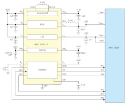
Maxim’s MAX14720 is a compact power-management solution for space-constrained, battery-powered applications where size and efficiency are critical (Fig. 9-7). This IC integrates a power switch, linear regulator, buck regulator, and buck-boost regulator.
The MAX14720 is intended to be the primary power-management device and is ideal for either non-rechargeable battery (coin-cell, dual alkaline) applications or for rechargeable solutions where the battery is removable and charged separately. The device includes a button monitor and sequencer.
9-7. Maxim’s MAX14720 is a compact power-management solution that integrates a power switch, linear regulator, buck regulator, and buck-boost regulator.
There are two programmable micro-IQ, high-efficiency switching converters: a buck-boost regulator and a synchronous buck regulator. These regulators feature a burst mode for increased efficiency during light-load operation.
A low-dropout linear regulator has a programmable output. It can also operate as a power switch that can disconnect the quiescent load of system peripherals.
This IC also includes a power switch with battery-monitoring capability. The switch can isolate the battery from all system loads to maximize battery life when not operating. It is also used to isolate the battery-impedance measurements. This switch can also operate as a general-purpose load switch.
The MAX14720 includes a programmable power controller that allows the device to be configured either for use in applications that require a true off state or for always-on applications. This controller provides a delayed reset signal, voltage sequencing, and customized button timing for on/off control and recovery hard reset.
This IC is available in a 25-bump, 0.4mm pitch, 2.26mm x 2.14mm wafer-level package (WLP) and operate over the -40°C to +85°C extended temperature range.
Multi-Function Battery Power-Management ICs
These ICs perform multiple functions in a battery-based system. Among these functions are battery charging, dc-dc conversion, battery protection, battery monitoring, and power-source selection.
For example, an IC integrates PWM power control for charging a battery and converting the battery voltage to a regulated output. Also, it can simultaneously charge the battery while powering a system load from an unregulated ac wall adapter. Combining these features into a single IC produces a smaller area and lower-cost solution compared to presently available multi-IC solutions. The IC shares the discrete components for both the battery charger and the dc-dc converter, minimizing size and cost relative to dual controller solutions. Both the battery charger and dc-dc converter use a current-mode flyback topology for high efficiency and excellent transient response. Optional Burst Mode operation and power-down mode allow power density, efficiency, and output ripple to be tailored to the application.
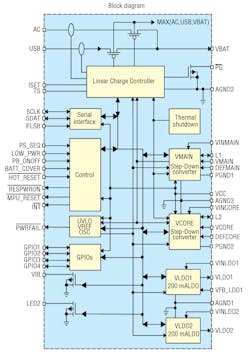
9-8. Texas Instruments’ TPS65010 is an integrated power-supply and battery-management IC.
The IC provides a complete Li-Ion battery charger with charge termination timer, preset Li-Ion battery voltages, overvoltage and undervoltage protection, and user-programmable constant-current charging. Automatic battery recharging, shorted-cell detection, and open-drain C/10 and wall-plug detect outputs are also provided. User programming allows NiMH and NiCd battery chemistries to be charged as well.
TPS65010
Texas Instruments’ TPS65010 is an integrated power and battery management IC for applications powered by one Li-ion or Li-polymer cell, and which require multiple power rails (Fig. 9-8). The power source components include:
- 1A step-down converter for I/O and peripheral components (VMAIN)
- 400mA, 90% efficient step-down converter for processor core (VCORE)
- 2x 200mA LDOs for I/O and peripheral components, LDO enable through bus
- Serial interface compatible with I2C, supports 100kHz, 400 Hz operation
- 70µA quiescent current
- 1% reference voltage
- Thermal shutdown protection
The TPS65010 charger automatically selects the USB port or the ac adapter as the power source for the system. In the USB configuration, the host can increase the charge current from the default value of maximum 100 mA to 500 mA through the interface. In the ac-adapter configuration, an external resistor sets the maximum value of charge current. The battery is charged in three phases:
- Conditioning
- Constant current
- Constant voltage
Charge is normally terminated based on minimum current. An internal charge timer provides a safety backup for charge termination. The TPS65010 automatically restarts the charge if the battery voltage falls below an internal threshold. The charger automatically enters sleep mode when both supplies are removed.
Read more articles from the Power Management Series in the Power Management section of our Series Library.

