Multiphase Boost Converter Powers Car Audio Amp
Automotive audio amplifiers often use a boost converter to generate output voltages of 18 V to 28 V (or higher) from the battery. In these high-power applications of 100 W and above, large boost inductors, banks of output capacitors, and paralleled MOSFETs and diodes are required. Splitting the power stage into multiple paralleled phases reduces stress on the power components, speeds up the response to load changes (like those big bass notes) and improves system efficiency.
It is relatively easy to find a pulse-width modulation (PWM) controller for use in a 2-phase boost converter. Most dual-interleaved off-line controllers or push-pull controllers can be used to directly drive two boost MOSFETs out of phase. However, in 4-phase solutions, the controller choices are much more limited. Fortunately, some multiphase buck controllers can be easily adapted for use in a 4-phase boost converter.
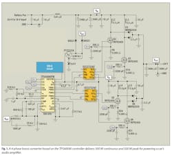
Fig. 1 shows a 4-phase, 300-W boost power supply using Texas Instruments' TPS40090 multiphase buck controller. This converter was designed to handle bursts of 500 W peak, which is typical in audio applications. Normally, in a multiphase buck configuration, the controller balances the power in each phase by sensing the average current in the output inductor. By contrast, in a multiphase boost configuration, the current is sensed across a resistor located at the source of each FET.
By balancing the peak current in each FET, the multiphase controller distributes power evenly in each boost phase. The gate-drive signals from the controller are logic-level, so each phase requires a MOSFET driver. In this design, a dual MOSFET driver such as the UCC27324 is used to reduce the number of components.
The multiphase controller protects the converter from overload conditions by imposing a current limit on each phase. Audio applications have short-duration peak power demands that are much higher than the average output power. The current limit must be set high enough to satisfy these peak power requirements.
Another level of protection is provided by an external undervoltage lockout (UVLO) circuit, which prevents operation during low battery conditions. As the battery voltage drops, the boost supply tries to draw more input current, which can lead to a quick collapse of the battery voltage as the battery is depleted. This scenario could lead to cell damage, or even worse, a dead battery. The simple and inexpensive UVLO circuit is composed of a reference, a dual comparator and a few resistors (not shown).
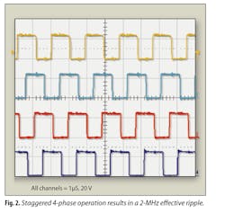
In this design, the four phases are switched at 500 kHz and are synchronized 90 degrees apart. Fig. 2 shows the drain-to-source voltage waveforms for all four phases. The ripple currents from each phase sum together at the input and output, where they partially cancel each other. This reduces the ac ripple currents in both the input and output capacitors. Additionally, the combined ripple currents occur at 2 MHz, four times the frequency of an individual phase.
Because of the reduced ripple currents and the higher frequency, the amount of input and output capacitances are much smaller in multiphase solutions compared to single-phase solutions. The higher effective switching frequency also allows the converter to respond faster to changes in load current.
The power stage of each individual phase is composed of a single inductor, MOSFET, Schottky diode and current-sense resistor. L2, Q2, R8 and one leg of D3, for example, comprise one phase. Compared to a single-phase solution, the power losses are less and spread out over a larger area, which simplifies thermal management. The reduced current and power ratings provide a wider selection of off-the-shelf inductors, FETs and diodes. This 4-phase design is 94% efficient when powered with a 300-W load, resulting in less than 20 W of loss.
The high efficiency enables this design to be packaged into a small form factor. For lighter-load power requirements, this design can be scaled down to two phases. In that case, a push-pull or interleaved-forward PWM controller could be used in place of the TPS40090. For higher power loads, the power components can be scaled up to handle the increased current and power dissipation. Sized appropriately, four phases should be sufficient to support any high-power audio application.


