BMW i3 Concept Car Relies on Wireless Feedback of Individual Battery Cell Performance
Electric vehicles employ battery management systems (BMS) that work in real time to monitor the performance of individual battery cells. That is, each cell must be monitored to ensure it is operating properly and that there is balanced cell load sharing. Besides managing battery operation, the BMS often has to handle other vehicle functions, including the vehicle's desired operating mode, whether it is accelerating, braking, idling or stopped, which can then activate appropriate power management functions.
Current generation electric vehicles manage batteries by monitoring individual battery cell performance connected to a central BMS master via cables and wiring harnesses. A new proposal from Linear Technology suggests that future vehicles will manage battery conditions with the help of a wireless BMS. It supplies individual battery cell performance feedback via wireless RF communication. Among the benefits of this wireless BMS are:
- Eliminates maintenance-prone connectors, cables and harnesses.
- Permits the addition of new sensors to improve reliability.
- Simplifies vehicle assembly and battery maintenance.
- Provides designers with additional mechanical design flexibility.
- Allows precise time-stamped data collection that can improve battery condition feedback.
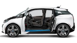
Linear Technology demonstrated the industry’s first wireless automotive battery management system (BMS) concept car at the recent Electronica Show in Munich, Germany. This wireless BMS concept car, developed by Linear’s design partner LION Smart, combines Linear’s highly accurate battery stack monitors with its SmartMesh wireless mesh networking products in a BMW i3, replacing BMW’s standard battery pack and BMS.
The BMS in the BMW i3 enables it to achieve a 114 mile range on a full charge, and reach 180 miles with a Range Extender. Achieving this range is also due to its relatively light weight, made possible by use of a strong yet lightweight Carbon Fiber Reinforced Plastic (CFRP) body that is 50% lighter than steel, but just as strong.
Another critical factor in optimizing this i3’s range is the use of a li-ion battery with higher energy density than the stock i3. For added efficiency, the vehicle incorporates braking energy regeneration that feeds back power to the li-ion batteries. To maintain the charge on its batteries is a gas-powered, two-cylinder engine that generates power at an approximate 5% level, based on EPA estimates.
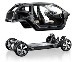
The BMW i3’s architecture uses a two-piece structure that increases agility, driving range, and interior comfort (Fig. 1). Li-ion batteries are between its front and rear axles, creating near-perfect 50:50 weight distribution and a low center of gravity for improved stability while cornering. Integrating the battery this way also frees up considerable space in the cabin above.
BMW i3’s Range Assistant monitors the batteries charge level, driving style, traffic situation and topographical information so it can tell the driver the most efficient route based on its current battery charge.
You can fully recharge the BMW i3’s batteries in 4.5 hours using a Level 2 charging station. In approximately 30-40 minutes, you can get up to an 80% charge with a DC Combo Fast Charger. Also available is a home-based charging station.
Li-ion batteries used in the BMW i3 require considerable care to ensure they operate reliably over a long period. For best results, they should not be operated at the extreme end of their state of charge (SOC). Every cell in a BMS must be managed to keep it within a constrained SOC because the performance of li-ion cells diminishes and diverges over time and usage.
Providing sufficient power for a vehicle requires multiple battery cells configured in a series string that can produce up to 1000V or more. Battery management electronics must operate at this high voltage and reject common mode voltage effects, while differentially measuring and controlling each cell in the string. Then, the BMS must be able to communicate information from each cell in a battery stack to a central point for processing.
Operating a high voltage battery stack in a vehicle imposes severe environmental conditions, such as electrical noise and wide operating temperatures. Despite these operating conditions, battery management electronics must maximize operating range, lifetime, safety and reliability, while minimizing cost, size and weight.
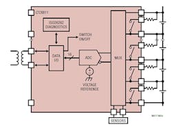
The BMS in the i3 concept car uses Linear Technology’s LTC6811 high voltage battery stack monitor (Fig. 2). It incorporates a deep buried Zener voltage reference, high voltage multiplexers, 16-bit delta-sigma A/D converters (ADC) and a 1Mbps isolated serial interface. A single LTC6811 can monitor up to 12 series-connected battery cell voltages with better than 0.04% accuracy. To minimize noise, there are settings for eight programmable third order low pass filters. In its fastest ADC mode, it can monitor all 12 cells within 290μsec.
The LTC6811 is fully specified for operation from 40°C to 125°C and is compliant with ISO26262 (ASIL). It has extensive fault coverage via its redundant voltage reference, logic test circuitry, cross-channel testing, open wire detection capability, a watchdog timer and packet error checking on its serial interface.
Support for the LTC6811 is available from Linear Technology’s Linduino™, an Arduino-based microcontroller board and software library. The microcontroller board directly connects to an LTC681demonstration board, providing a simple platform for evaluating and developing LTC6811 systems.
Distributing Battery Cells
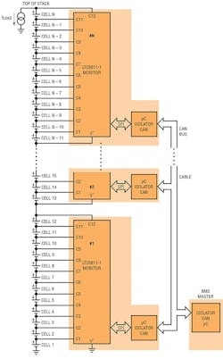
To accommodate the large number of cells required for high powered automotive systems, batteries are often divided into modules. Supporting a distributed, modular topology within the potentially high EMI environment of an electric vehicle requires a robust communication system. One battery interconnection approach is to use an isolated CAN Bus. The CAN Bus provides a well-established network for interconnecting battery modules, but requires a number of additional components when implementing it via the LTC6811’s SPI interface. Fig. 3 shows a typical CAN configuration for battery modules.
The downside of a CAN Bus configuration is the added cost and board space required for additional elements that include:
- CAN transceiver
- Microprocessor
- Isolator
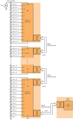
An alternative to a CAN Bus interface for the LTC6811 is Linear Technology’s 2-wire isoSPI™ interface that is integrated into the LTC6811. The isoSPI interface uses a simple transformer and a single twisted pair, as opposed to the four wires required by CAN bus. The isoSPI interface provides a noise-immune interface for daisy-chained modules connected over long cable lengths and operated at data rates up to 1Mbps. Fig. 4 illustrates use of an isoSPI interface for connecting multiple battery stack monitors.
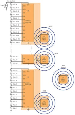
In the i3 concept car, this wireless BMS combines the LTC6811 battery stack monitor with Linear Technology’s SmartMesh wireless mesh networking products. The SmartMesh replaces the traditional hard-wired connections between the battery packs and the battery management system. A wireless BMS vehicle represents a significant breakthrough that offers the potential for improved reliability, lower cost and reduced wiring complexity for large multi-cell battery stacks in electric vehicles.
SmartMesh
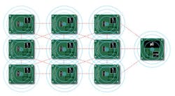
Automakers are challenged to ensure the driving public that electric vehicles are safe and reliable. The metal and high-EMI surroundings in vehicles were thought to be too harsh for a reliable wireless system. However, SmartMesh offers a truly redundant interconnect system through use of both path and frequency diversity to route wireless messages around obstacles and to mitigate interference.
Field-proven in industrial applications, SmartMesh embedded wireless networks deliver >99.999% reliable data transmission in harsh environments. By eliminating mechanical connector failures, a wireless BMS vehicle holds the promise of significantly improving a vehicle’s reliability while simplifying its design and manufacture.
A BMS with a SmartMesh network also has the potential for new functionality, currently unavailable in a hard-wired system. The wireless mesh network enables the flexible placement of battery modules, and makes possible the installation of sensors in locations previously unsuitable for a wiring harness. Additional data related to the accuracy of battery state of charge (SOC) calculations, such as current and temperature, may be provided by simply adding SmartMesh enabled sensors.
SmartMesh automatically time synchronizes each node to within a few microseconds, and accurately timestamps measurements at each node. The ability to time-correlate measurements taken at different locations in a vehicle is a powerful feature for accurately calculating the battery state of charge (SOC) and state of health (SOH). A SmartMesh node with local processing at each module improves normal BMS operation, and also presents the potential for smart battery modules, where module diagnostics and communication may be available to enhance assembly and service.
These SmartMesh wireless sensor networks are self-managing, low power internet protocol (IP) networks built from wireless nodes called motes. The LTC5800-IPR is the IP Manager-on-Chip in the Eterna family of IEEE 802.15.4e system-on-chip (SoC) solutions, featuring a highly integrated, low power radio design by Dust Networks as well as an ARM Cortex-M3 32-bit microprocessor running Dust’s embedded SmartMesh networking software.
The LTC5800-IPM is the IP mote product in the Eterna family of IEEE 802.15.4e System-on-Chip (SoC). The LTC5800-IPM SoC features an on-chip power amplifier (PA) and transceiver, requiring only power supply decoupling, crystals, and antenna with matching circuitry to create a complete wireless node.
SmartMesh wireless sensor networking products are chips and pre-certified PCB modules complete with mesh networking software, enabling sensors to communicate in severe industrial environments.
SmartMesh Features:
- Field proven reliability in Industrial applications
- Time synchronized, channel hopping mesh technology automatically mitigates faults based on self-diagnostics
- Robust security includes NIST-certified AES128 encryption
SmartMesh is a product of Dust Networks that Linear Technology acquired in 2011. Dust Networks technology combines low power, standards-based radio technology, time diversity, frequency diversity, and physical diversity—to ensure an easy-to-use reliable, scalable, and flexible wire-free power source.
