You may not be able to find a commercially-available power management IC (PMIC) that meets your application’s requirements, but there is a way to get the device you need. You can use a new “do-it-yourself” (DIY) design technique, developed by AnDAPT (www.andapt.com), that employs a library of selectable power component building blocks, which in turn are built using analog elementary blocks that can interface with each other. They are offered on an Adaptive Multi-Rail Power (AmP) platform IC. After you select all the desired power component building blocks, software interconnects the analog elementary blocks (called µAnalog by AnDAPT) and creates a ready-to-use monolithic IC tailored to the requirements of the particular application. It’s all transparent to you.
The basic PMIC design process involves the following steps:
1. Determine the requirements for the desired PMIC.
- Circuit functions
- Input pins
- Output pins
2. Access cloud-based AnDAPT WebAmP software on a PC browser.
- AmP IC Platforms
- Power components building block library
- WebAmP Compiler
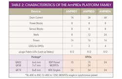
3. Select the required platform from Table 1, according to the required number of power blocks, I/Os, and output current.
4. As an example, select the AmP8D6 shown in Fig. 1. Once you select the AmP8D6 platform on the PC screen, the WebAmP tool displays the power component building blocks library. You click on each power component category to list available power components.
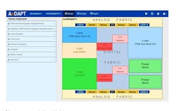
5. Drag-and-drop power components from the library onto the AmP8D6 platform (Fig. 2) as needed by your application. This platform shows an example eight power component building blocks that have been selected:
- PWM Async Buck Voltage Mode
- Load Switch
- LDO-DDR
- PWM Sync Buck Current Mode
- Sequencer × 2
- Reset Generator × 2
6. Double-click on each power component in Fig. 3 to highlight features defined via on-screen options, which enables the designer to optimize the power component to the specific application. Using available tools, designers can optimize and tune the power components for stability, transients, efficiency, and startup/shutdown characteristics.
7. A suite of Power Analysis tools helps the optimization, including:
- LC Calculator
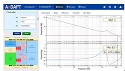
- Stability analyzer presenting a Bode plot with gain and phase margin, as shown in Fig. 3
- PID tuning
- Transient response calculator
- Efficiency calculator
- AmPScope to monitor and debug rails in circuit, in real time (coming soon)
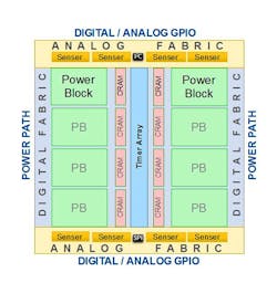
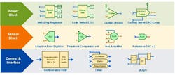
8. As shown in Fig. 4, AmP Platform IC packages consists of the following elementary building blocks: eight power blocks, eight sensor blocks, and digital logic/connectivity. Power Blocks are used for building various topologies, including:
- Scalable Integrated N-channel MOSFETs (SIMs)
- Current sense for protection, telemetry, regulation
- Switching topologies - Buck, Boost, Buck-Boost
- Linear topologies - LDO, Load Switch
- Mixed topologies - Battery Charger
- BLDC topologies – H-Bridge
Sensor Blocks are used for sensing voltages and currents, including:
- Adaptive Digitizer (ADi)
- Threshold Comparators (ThC)
- Summation AMplifier (SuM)
- Noise-Immune Reference (Nref) Array
- Regulation, protection, and telemetry
- Analog fabric connectivity for sensor signals
Digital/logic connectivity:
- Analog and Digital GPIOs, LUTs for logic and Interface
- Integrated Compensator RAM (CRAM)
- POL control loops and interfaces
- Precision Modulation Timer Array
In addition, analog elementary blocks (µAnalog) can be used for motion control systems driving:
- BLDC Motors
- Servo-stepper
- Fan Controllers
9. When all components are installed, you compile the PMIC design data with the associated AnDAPT WebAmP compiler and store it in the PC.
10. Behind the scenes, the WebAmP Compiler uses power component’s Verilog descriptions for the design and verification of analog and mixed-signal circuits, in a manner similar to that used for FPGAs. Verilog, standardized as IEEE 1364, is a hardware description language (HDL) used to model electronic systems.
11. Obtain the appropriate AnDAPT blank AmP Platform IC package whose silicon substrate will hold the final circuit.
12. Download the Verilog-compiled data from the PC to the AnDAPT blank AmP Platform IC programming fixture using the AmPLink USB adapter. The compiled data will be used to produce each of the analog circuits as well as interconnecting them.
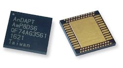
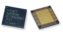
13. The end result is a monolithic PMIC, as shown in Fig. 6.
14. The product family is offered in QFN packages with 6×6, 7×7, and 8×8 footprint sizes. Initial device AmP8DS6QF74 is available in a 74-pin, 8-mm-by-8-mm-by-0.85-mm thermally enhanced QFN package. The lowest-cost member of the family AmP8DP1QN52 is priced at US $3.75 in 1,000-unit quantities. WebAmP tools and power components can be licensed online and are available for a 30-day free trial period.
