Providing modern electronic devices with a diet of healthy power is not straightforward. Small AC-connected equipment often uses a capacitor-input filter following a half- or full-wave rectifier. Because current is drawn for only a small portion of the voltage cycle, the power factor (PF) is low, and the crest factor (CF) is high. For battery-powered products, current may be demanded in bursts, corresponding to periods of higher computational activity. It’s important that power sources are compatible with load characteristics such as these.
DC loads
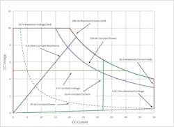
As the B&K Precision 8500 Series DC Electronic Loads datasheet states, wide voltage and current ranges, flexible operating modes, and accurate measurements make the series well-suited “… for characterizing DC power supplies, DC-DC converters, batteries, fuel cells, and solar cells.” Figure 1 shows the operating area for a hypothetical 200-W DC load as well as examples of several operating modes.
For this load, the maximum voltage is 10 V, and the maximum current is 50 A. The hyperbolic curved red-purple-green portion is the locus of I-V combinations satisfying the 200-W maximum power limit. The distance between the lower boundary condition and the horizontal axis is the minimum voltage required at a given current and results from the load’s 0.01-Ω internal resistance.
The constant resistance (CR) mode simulates a 0.4-Ω resistor. However, for currents greater than about 22.4 A, the power dissipated would exceed 200 W, so the CR mode follows the 200-W hyperbola for larger currents. Similarly, the 5-V constant voltage (CV) line can be sustained for any current less than 40 A, above which it too follows the 200-W hyperbola. In operation, the current corresponding to an applied voltage less than 5 V will fall along the vertical axis—zero A. For inputs larger than 5 V, the load will draw sufficient current, up to a maximum of 40 A, to pull the supply output down to 5 V. For a source like a 6-V car battery, which has an internal resistance similar to the load’s own 0.01 Ω, the load would limit at about 33 A to 34 A because the car battery output will reduce only slightly from 6 V at this current level (6 x 33 ≈ 200 W).
The constant current (CC) mode really is a current limit with a maximum power constraint. For this example, the current limit has been set to 32 A. So, if you apply a voltage to the load, it will act like a very low resistance until the current reaches 32 A. This can be a dangerous mode unless your supply has its own internal current limit set to protect it. Assuming the supply can provide more than 32 A without damage, the load will sink that much current until the corresponding input voltage increases to a little more than 6 V, at which point the 200-W limit takes over. Going back to the car battery example, if the CC setting were 40 A, the load still would operate close to the 6-V, 33-A point. The 40-A limit never would be reached because of the car battery’s extremely low internal resistance 6-V output.
In general, constant power (CP) corresponds to a hyperbolic curve. The extent of the curve depends on the load’s maximum voltage and current limits. For Figure 1, the 25-W CP hyperbola extends from the bottom right corner at 0.5 V, 50 A to a point at 2.5 A along the 10-V maximum voltage limit. The shortest hyperbola corresponds to the load’s 200-W maximum power.
GW Instek’s PEL-3000 Series of DC loads has three additional “+CV” modes that combine CV with CC, CR, or CP selections. The idea is to give the user more control over the test conditions rather than allow the load’s maximum limits to control events. For example, in CC+CV mode, the load will sink current up to the preset value. In power supply testing, CC load settings are used to exercise the supply’s current limit. However, when many supplies go into current limit, they switch to CC operation. Rather than continue drawing the maximum current, switching the load to CV mode allows the load to shut off when the supply drops its output voltage below the +CV setting on the load. Similarly, CR or CP modes can switch to a preset CV level rather than the load’s maximum limit.
DC loads typically have a bandwidth specification and may list a maximum slew rate. These parameters are important if you want to determine a power supply’s response to a load transient or if you need to simulate a CC load that has some high-speed variation. For example, according to the datasheet for Ametek Programmable Power’s Sorensen brand SL Series of DC loads, an analog input “… allows arbitrary current waveforms up to 20 kHz with an external 0-10 V signal. In dynamic mode, the pulse generator allows fast state switching between two programmed current levels with programmed slew rate and dwell times.”
AC loads
Although AC and DC loads use many of the same mode names—CR, CC, CP—there are basic differences. Current in an AC load is AC and has a phase relationship to the input voltage. For a linear load, you can specify the phase angle or the corresponding lead/lag displacement power factor. Modern equipment often presents a nonlinear load, which develops current harmonics in addition to the fundamental component. For these loads, a multiplicative distortion power factor can be calculated based on the total harmonic distortion.
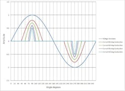
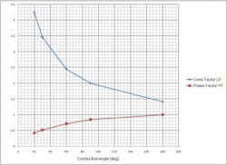
In general, it’s easier to consider the fundamental definition of PF: PF = real power/apparent power = real power/(Vrms x Irms). Figure 2 shows several nonlinear current waveforms with conduction angles from 90 degrees to 20 degrees, and Figure 3 displays the corresponding PFs and CFs: CF = peak/rms.
In Figure 2, the phase angle between the voltage and current waveforms has been kept at zero to simplify the discussion. However, if a phase lead/lag is introduced, the real power will be reduced while the rms values will be unchanged. Real power is equal to the product of instantaneous voltage x instantaneous current. If the phase shifts away from zero, the current waveform will be multiplied by a lower amplitude portion of the voltage waveform.
Figure 2 shows half cycles of sine waves: 2 x frequency for 90 degrees conduction, 3 x for 60 degrees, 6 x for 30 degrees, and 9 x for 20 degrees. The waveform amplitudes arbitrarily have been adjusted to make the figure easier to understand. As described in the datasheet for Ametek’s California Instruments brand 3091LD AC load, “When operating in constant current or constant power mode, the 3091LD supports crest factor control by narrowing the conduction angle of the current waveform in order to match the requested crest factor. Consequently, as crest factor is increased, the true power factor automatically decreases. The load further controls power factor by shifting the current with respect to the input voltage (displacement power factor).”
Chroma Systems Solutions’ Model 63800 Series of AC and DC loads has an added DSP-enabled RLC mode that simulates a full-wave rectified circuit. Series inductance can be added ahead of the rectifiers and a capacitor placed in parallel with the load resistance. In RLC CP mode, the DSP algorithm will calculate the appropriate R, L, and C values if the load power and PF are specified. For input frequencies up to 70 Hz, the corresponding V and I waveforms are calculated in real time. A further inrush mode simulates the high-level current pulses typically generated when power first is applied to a capacitor-input rectifier circuit.
NH Research’s 4600 Series of AC loads features user-defined current waveforms. As stated in the datasheet, “The graphical editor includes an auto-check feature to ensure the settings are compatible with each other and within the capabilities of the load.” This is important because, as shown in Figure 3, PF and CF are related. The 4600 loads support lead/lag PF from 0 to 1.0 and CF from 1.414 (sine wave) to 4.0. Chroma’s 63800 loads allow CF up to 5.0.
For large power applications, dissipation quickly becomes a problem. Both DC and AC load manufacturers have developed regenerative systems that, instead of wasting energy as heat, return up to 90% of the power to the AC mains. Intepro Systems’ 60-kVA PEL Series is a good example of a regenerative AC load intended for use in the power industry. Generator and motor/turbine manufacturing requires burn-in as well as performance testing. Electronic products such as UPS, frequency converters, voltage regulators, and power inverters all need to be tested at high power levels. For these applications, the PEL Series offers CC, CR, and CP modes for inputs from 120- to 480-Vrms at 45 to 65 Hz.
Kikusui Electronics’ Model PCZ1000A AC load also supports CC, CP, and CR modes with a 1-kW maximum power limit. In addition, it allows selection of the current CF from 1.4 to 4.0 to simulate the operation of a switch-mode power supply.
Conclusion
The choice of a DC or AC load can be complicated. Beyond the usual voltage, current, and power limits of a DC load and the added CF, PF, and frequency specifications for an AC load, each manufacturer has included some special modes or features. One of these could be exactly what you need to address your present application. Of course, you may need something else entirely for the next project. Nevertheless, exploring the “additional” features can help to distinguish among models with similar basic performance.


