This article appeared in ElectronicDesign. It is reprinted here with permission.
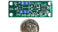
You can use supercapacitors as a storage element for energy harvesting (Fig. 1). They’re also used to store energy for camera flash circuits. Electric cars and hydrogen fuel-cell cars might use supercaps to provide a low-impedance reserve for fast acceleration and store a large amount of power from regenerative braking systems. The virtue of supercaps in electric vehicles was validated by Tesla’s acquisition of supercapacitor maker Maxwell Technologies in 2019.
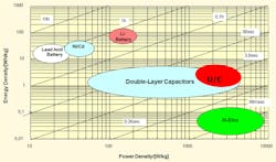
Another use for ultracaps is energy storage for the electric grid. Batteries are good for energy storage; they hold a lot, but you can’t discharge them fast. Supercaps are good for power storage. That is, they can deliver a smaller amount of energy in a short period of time. Power is energy over time, so you will often see supercaps and batteries in a paralleled architecture, where the system can store and accept a lot of energy as well as deliver and absorb a lot of power (Fig. 2).
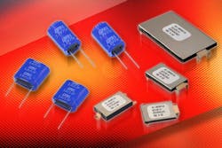
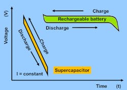
Supercapacitors useful for electronics can have as much as 3000 F in capacity. That’s a lot of energy, rivaling small batteries. The headache is that when a supercap discharges, it has a linear reduction in output voltage. Another problem with supercaps is that they tend to come in low operating voltages; 2.7 V is a typical value (Fig. 3). For this reason, it’s common to make a series string of two or more supercapacitors to achieve a more useful working voltage.
Series-Connected Problems
The problem with series-connected supercaps is that the voltage across each capacitor cell will not be the same. The first issue will be the tolerance of the cells themselves. Many manufactures have ±20% tolerance. So, if you’re unlucky enough to series a high-tolerance cell with a low-tolerance one, you will have a voltage imbalance across the cells that’s sure to over-voltage one cell. Remember, when you do high-volume manufacturing, you’re always “lucky” when it comes to these unlikely occurrences.
Cell manufactures consider an over-voltage a form of abuse. It will lead to capacitance loss, an increase in equivalent series resistance (ESR,) bulging, possible venting, electrolyte decomposition, gas generation, and ultimately reduced life. Other forms of cell abuse are over-temperature and excessive mechanical stress. They will lead to the same adverse conditions.
Resistor Balancing
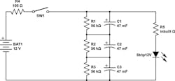
A simple way to balance a string of supercaps is with paralleled resistors (Fig. 4). A rule of thumb is the same factor-of-ten that you use to make an unloaded voltage divider. Whatever the leakage current of the supercap, you use a parallel resistor that has 10X the current at the nominal cell voltage.
This approach has several problems, though. It doesn’t solve the tolerance imbalance problem, and it adds resistor tolerances to the capacitor tolerance problem. The resistors will draw current that must be supplied or it will discharge the capacitor string. They also won’t allow for variations in supercap leakage over time and temperature.
FET Balancing
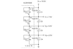
A far preferable solution is to use carefully-chosen FETs that will turn on slightly as the capacitor cell approaches the operating rated voltage (Fig. 5). The FET manufacturer can control the threshold voltage with ion implantation of a floating gate, or by process, or by hand-selection. With ion implantation, you get a more predictable and precise current at the cell voltage—the parts are screened for this in testing, so you can consider them pre-selected for your application.
Active balancing with FETs is a more direct solution. The FETs will regulate the cell voltage and even account for aging and temperature changes. Be sure to characterize your supercapacitor cells over time, over temperature, over shock, and over any other factors that you think might affect them, including sunlight, altitude, radiation, or other application-specific environmental variables.
Dynamic Stack Monitoring
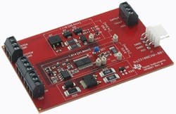
A more advanced form of active balancing uses a chip that measures the cell voltages and applies the proper shunt currents to keep the cell balanced (Fig. 6). A chip like Texas Instruments’ BQ33100 can balance 2, 3, 4 or 5 capacitors. It will supervise up to a 9-capacitor string. It’s useful for applications like blade computers, medical equipment, uninterruptible power supplies, and RAID storage systems.
Companies such as Analog Devices also have chips that will charge, monitor, and balance supercapacitor arrays. Dialog Semiconductor makes supercapacitor management chips, too, and has a wealth of information on applying these circuits.
Out-of-the-Box Solution
Due to some of these hassles with series capacitors, you might consider just using one higher-value cell and then incorporate a boost converter to increase the 2.7 V to something you can use. Since the capacitor voltage will drop linearly with discharge, you may need a switching boost regulator anyway.
While not many buck regulators operate from 2.7 V, you might be able to use a higher-voltage rail to power the regulator chip. Another solution would be to fashion a boost circuit from discrete transistors. If you can afford to use one of the management chips, many come with buck-boost conversion included.
No matter if you deal with a balancing problem with resistors, FETs, or chips, you will be making a more robust energy-storage system. Similar concerns exist with strings of battery cells, and there are balancing chips and schemes for those as well. What you learn from balancing supercaps can be applied to batteries and other power-storage architectures.
Always remember that stringing components together is never as easy as it looks on a schematic page. Also be aware that if you want to model these strings in Spice, you have to model the cell-by-cell variations and temperature variations. You might be better off with real cells and a temperature chamber. An ounce of trial is worth a pound of theory.
