Designing Low-EMI Switched Capacitor ICs for the IoT (Part 2)
This article is part of the TechXchange: Delving into EMI, EMC and Noise.
Members can download this article in PDF format.
What you'll learn:
- What causes EMI in switched-mode power supplies, and how the active EMI filter can help.
- What is switching noise jitter?
- Adopting visible light communication to tackle EMI.
- Why AEFs are a better alternative for power-supply filtering.
For Part 1, go here.
Circuit designers need to pay close attention to potential electromagnetic-interference (EMI) sources in their design architecture in the early stages of the design phase.
For example, the switched-mode power supply (SMPS), a.k.a power conditioning unit (PCU), is a very efficient source of power for electronic designs. The caveat here is that when the power MOSFETs switch, it will likely become a major source of EMI in the SMPS. Often, this will lead to circuit reliability troubles, especially in spaces like the IoT.
EMI Sources in the SMPS
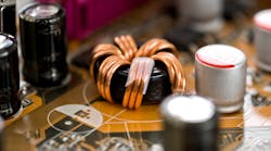
Typically, EMI rears its head when there are discontinuous input currents, fast slew rates on switching nodes, and nasty ringing along switching edges, mostly caused by parasitic inductances within the power loop (Fig. 1).
In the SMPS, voltages and currents get switched to control and shape the power to match load requirements, thus giving rise to electromagnetic fields that become associated with the environment around them, i.e., EMI.
Circuit designers need to deploy all of their tools to minimize EMI, particularly through simulation during the initial design phase. This will reduce the cost of hardware verification and boost productivity.
The Active EMI Filter
The active EMI filter (AEF) acts as a capacitance amplifier that’s able to provide as much as 30 dB of additional EMI attenuation. This greatly helps designers meet Comite International Special des Perturbations Radioelectriques (CISPR) 11, CISPR 32, and CISPR 25 EMI requirements.
The AEF is also able to reduce the inductance value of chokes in common-mode filters by as much as 80%. AEF integrated circuits diminish the size, weight, and cost of EMI filters, especially within high-power-density design solutions. Chokes will be 50% lower in size, more cost-effective, as well as lighter in weight.
AEFs will extend capacitor life by shrinking the sizes of magnetic components as well as reducing the level of heat generated while improving system reliability.
Switching Noise Jitter
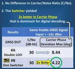
Switching noise Jitter (SNJ) is defined as a noise found in the time domain and is the dominant noise detrimental to digital systems. One method of reducing noise is via the patented TransSiP PI technology, which is designed to create high-quality DC power sources.
TransSiP PI helps to achieve improved system efficiency and performance that can actively identify and correct a newly found SNJ in real-time, thus providing a more stable, clean power signal (Fig. 2).
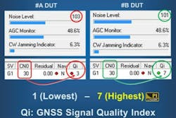
In one example, a switcher under test yielded the best digital quality signal even under a weak signal (Fig. 3).
Visible Light Communication
Radio-frequency (RF) communication can be severely affected by EMI. One way to overcome it is by leveraging visible light communication (VLC), a promising technology that supports lower EMI, high speed, high data rates, low cost, and low latency, along with the added bonus of a license-free spectrum.4
VLC employs ultra-low-power light-emitting diodes (LEDs) for transmission and photodetectors for receivers, enabling high-energy efficiency that’s comparable to traditional wireless communication technologies. An IoT over VLC, with a license-free spectrum, high spectrum efficiency, ultra-low latency, and high reliability, has gained the attention of industries and tech researchers.
Power-Supply Filters
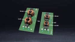
One of the main challenges for circuit designers in lowering EMI is the existence of large passive filters in power-supply systems. This is another case where AEF ICs can be employed, as they’re able to function as capacitance amplifiers. It will enable additional EMI attenuation, as high as 30 dB, and can reduce choke inductance value by as low as 80% in common-mode filters (Fig. 4).
AEF ICs help shrink the cost, size, and weight of EMI filters over large passive filters in high-power-density solutions. They’re composed of active devices that will control and sense voltage or current disturbances by injecting an opposing signal, which will cancel out most of the noise. AEFs offer many advantages over passive filters:
- A much simpler structure, as compared to most filters.
- They enable wider operating frequencies.
- A smaller common-mode choke size leads to lighter weight, lower cost, and smaller power supplies.
- Reduced parasitic inductor losses.
- Generate less heat as compared to passive filters, improving reliability and lifetime of the filter capacitors.
- Meet line-voltage surge immunity, as per the IEC 61000-4-5 standard.
- Don’t require additional magnetic components.
- Standalone solution that will provide greater flexibility in PCB design.
- It’s low voltage is referenced to chassis ground, improving safety.
Summary
AEF ICs sense high-frequency noise on each power line, via the use of a set of sense capacitors, and inject noise-canceling currents back into the power lines via the use of an injection capacitor. Capacitive amplification is employed in designs to increase the net active capacitance, thus lowering the common-mode choke values and size for a target filter attenuation.
Read more articles in the TechXchange: Delving into EMI, EMC and Noise.
References
1. “Accelerating IoT Designs: Designing for Low Power in the Era of Smart Everything, Synopsis,” Ron Lowman, 2022.
2. “Time-Saving and Cost-Effective Innovations for EMI Reduction in Power Supplies,” Texas Instruments, 2021.
3. TransSiP solutions.
4. “Bandwidth and Power Cost Optimized MAC Protocols for IoT over VLC,” 2020 IEEE-HYDCON.


