Automotive-Grade MCU Controls Brushless DC Motors
A new family of motor-control MCUs from NXP Semiconductors is designed to “rev up” brushless DC (BLDC) and other electric motors that are becoming more widely used in modern cars and industrial motor drives.
While its S32K family of MCUs targets the traction motors at the heart of electric vehicles (EVs), the automotive chip giant said the new S32M2 primarily focuses on various other motors used in cars to automatically open and close trunks or windows and adjust seat positions or side mirrors. Instead of using the same system-on-chip (SoC) approach as the S32K, the S32M24x and S32M27x bring a wide range of power and analog features inside a system-in-package (SiP) engineered for motor control.
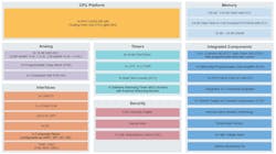
At the heart of the S32M2 is a single-core Cortex-M4 CPU clocked at up to 80 MHz or Cortex-M7 clocked at 120 MHz, paired with a single-precision floating-point unit (FPU). That gives it more performance than its predecessors to handle more advanced motor-control software, which can be updated over time to run motors more quietly and efficiently. The MCU is supplemented by 128 kB to 1 MB of on-chip memory.
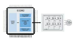
By integrating the power circuitry used to drive the motor and analog circuitry that controls it in a 64-pin LQFP package, NXP said the S32M2 saves space on the printed circuit board (PCB) and reduces design risks.
A New MCU for Advanced Motor Control
Compared to the many types of “brushed” electric motors, BLDC motors and permanent-magnet synchronous motors (PMSMs) stand out for being smaller, lighter, quieter, and more robust.
Though they also tout higher endurance and better power efficiency, there are tradeoffs. Since it uses electronic motor control, integrating a BLDC motor into a system tends to be a more complicated task.
Most electric motors have rotation produced by the interaction of magnetic fields, one produced by the rotor (the rotating part of the motor) and the stator (the part of the motor that’s fixed in place). One (or both) sets of these magnets are made from a coil of wire wound around a core. The current running through the wire windings creates a magnetic field, contributing power that runs the motor.
In brushed DC motors, current passes through the coils that form the rotor, creating a magnetic field. As each coil is repelled from the permanent magnet around it with the same polarity and pulled toward the magnet with the opposite polarity, the motor windings start spinning. To maintain the rotation, it’s necessary to continually reverse the current so that the polarity of the magnetic field in the coils will constantly flip, causing the coils to “chase” the permanent magnets placed around it.
Power to the coils is supplied through “brushes” that make contact with a rotating commutator at the center of the motor. The commutator is what causes the reversal of current traveling through the coils. The tradeoff is that friction between the stationary brushes and the commutator on the rotating part of the motor causes wear. Excess power can be lost due to insufficient brush-to-metal contact and arcing.
Instead of using brushes to commutate the motor and cause it to rotate, BLDC motors use more advanced electronic control techniques. The MCU at the heart of the system controls the gate driver that propels the FETs supplying current to the motor’s windings. The current creates magnetic fields in the stator coils that rotate in space, which the rotor—now a permanent magnet—follows.
The MCU is used to alter the phase and amplitude of the current and send it to the coils at the correct time and in the right order. Precise timing allows for more accurate control and makes sure the motor runs at peak efficiency.
To reduce power losses, it’s necessary to keep close tabs on the operating characteristics of the motor and use the feedback to fine-tune the pulse-width-modulation (PWM) signals that control the MOSFETs supplying power to the motor. NXP said the S32M2 is equipped with a wide range of I/O to connect to sensors that monitor the position and operation of the motor. It also adds integrated current sensing.
The high-performance MCU cores inside the S32M2 control the speed and torque of the motor more carefully. In addition, high-speed analog peripherals include timers and high-precision analog-to-digital converters (ADCs) to condition and output PWM signals that control the motor. The chips bring LIN, CAN FD, and CXPI communication interfaces to the table to connect to the vehicle’s other systems.
Gate Driver Takes Care of the Power Delivery
NXP said the S32M2 delivers enough performance to handle more advanced forms of motor control, including state-of-the-art field-oriented control (FOC). Instead of using sensors to sense the position of the motor, FOC senses the voltage in the windings—typically wired into three groups, turning it into a three-phase motor driven by three half-bridges—and uses the feedback to adjust the motor-control outputs.
The S32M2 integrates a three-phase gate driver that drives up to six external power MOSFETs, giving it the ability to control a single three-phase BLDC (or PMSM) motor or up to three single-phase brushed DC motors at the same time.
A gate driver is one of the main building blocks of a motor-control system, as it’s used to supply voltage and current to the windings in electric motors, and in turn, achieve the desired speed, torque, direction, and other operating characteristics. The gate driver acts as the interface between the MCU that outputs PWM signals to manage the duty cycle, frequency, and deadtime of the power FETs that run the motor.
In general, increasing the slew rate (dV/dt) of the power FETs driving the motor ends up improving the dynamic response times of the system, resulting in more accurate control of the PWM. Increasing the slew rate is preferable to reduce dead time and related power losses during switching. But the tradeoff is that these fast transitions can cause excess electromagnetic interference (EMI) and other electric noise.
NXP said the MCU’s gate driver has a programmable slew rate to meet different requirements. A voltage regulator is also part of the automotive-grade package so that it can run directly from the 12-V battery.
Software Reuse: Pivotal for NXP’s S32 Platform
The S32M2 is based on the same underlying architecture as the other offerings in NXP’s S32 platform, giving its customers the flexibility to maximize software reuse between different generations of cars.
In addition, the S32M2 is fully compatible with the company’s existing software and development tools, said Manuel Alves, SVP and GM of general-purpose and integrated automotive processors at NXP. According to the company, the S32M2 has more than enough performance to run diagnostics on the motor it controls as well as run software applications on top of AUTOSAR. Firmware over-the-air (OTA) updates are also possible.
The S32M2 supports ASIL B functional safety under the ISO 26262 standard, and it brings NXP’s hardware security engine (HSE) and other security subsystems (CSEc) plus secure boot into the fo


