Magnetic Energy Harvester Features Design Insight—and Tradeoffs
What you’ll learn:
- The three broad challenges in a low-level energy-harvesting design.
- How circuit-design supplies affect energy-harvesting system topology.
- How tests reveal performance of the system from various perspectives.
Technical success can be initiated by a dramatic breakthrough or innovation, but it can also be the result of conscientious design with careful attention to execution details. We rely on both for progress. The latter is the case with a recent energy-harvesting project at MIT.
A team developed a system and circuit that uses a low-power energy-management module as the interface between a clampable, split-core, current-transformer (CT) magnetic energy harvester (MEH) and an off-the-shelf Bluetooth Low Energy (BLE) embedded hardware sensor kit. The transformer clamps around an AC current-carrying conductor and harvests energy from the surrounding magnetic fields.
Viewed by itself, this project doesn’t break any R&D ground, although it includes some clever subcircuits. But the team has gone further than just describing what they did as a simple “project report.” Their paper includes details of the issues they addressed and the tradeoffs they assessed. It acts as a guide and roadmap for an energy-harvesting system to assist the designer in balancing the available energy in the environment with the sensing needs.
3 Main Issues in Energy-Harvesting Design
In their work, they address the three major problems which designers of such harvesting projects face:
1. The system must be able to cold-start and fire up its electronics despite absence of an initial available voltage. They accomplished this with a network of ICs and transistors that enable the system to store energy until it reaches a certain threshold. The system will only turn on once it stores enough power to fully operate.
2. The system must store and convert the energy it harvests efficiently. They make the case for using a supercapacitor in this design rather than a battery for a variety of reasons, including lifetime cycling and safety. Sizing the supercapacitor is also a tradeoff, as it must be large enough to store sufficient energy for the device to turn on, but small enough that the initial charge-up phase doesn’t take too long.
3. Finally, there’s the issue of management. They developed a set of algorithms to dynamically measure and budget the energy collected, stored, and used by the device. It constantly checks how much energy is stored and infers whether to turn the sensor on or off, take a measurement, or push the harvester into a more advanced mode so that it can gather more energy for more complex sensing needs. It implements a scheme analogous to maximum power point tracking (MPPT) via the electronic load. Therefore, it can maximize the amount of power it’s harvesting and match the harvest to the needs of the sensor.
Magnetic Energy Harvester: From Theory to Execution
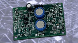
To test out their assumptions and tactics, they used off-the-shelf components to build an energy-management circuit for a temperature sensor. Their device harvests magnetic field energy and uses it to continually sample temperature data, which it sends to a smartphone interface using Bluetooth (Fig. 1).
This energy-management interface includes dynamically controlled rectification circuitry; DC voltage and current sensing for use in an energy-harvest enhancement algorithm and overvoltage protection; discrete “glue logic” for handling startup conditions; DC-DC converter stages; a comparator used as a gate driver; and an MCU to manage energy flow throughout the system as well as service a wireless sensor load.
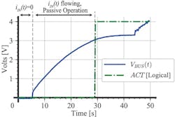
The system operates in its passive state during startup, using ultra-low-power logic to ensure the capacitive energy storage (COUT) can charge to an acceptable level before enabling downstream circuitry, including the DC-DC converter powering the MCU. Once the capacitive energy storage is sufficiently charged, the system switches into its active state. In this stage, the power supply for the MCU is enabled, and the MCU begins to perform energy enhancement and management tasks.
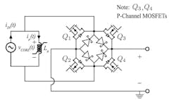
The hardware used to rectify the AC voltage, which is produced by the harvester core, to provide DC voltage VBUS across COUT (two 100-mF supercapacitors in series) consists of a full bridge using Schottky diodes. Each diode is in parallel with a MOSFET that’s used for active rectification once the system enters its “active” state (Fig 2).
The MCU provides the logic signals for controlling each MOSFET in the rectifier. A MAX934 comparator is used as a gate driver for level-shifting the 0- to 1.8-V logic-level signals from the MCU to 0 V to VBUS logic for driving the MOSFET gates directly.
During startup, though, the MCU is disabled. Neither the logic-level signals from the MCU nor the MAX934 outputs that will eventually be essential for energy enhancement during active operation are driven to a reliable on or off state. The ultra-low-power glue logic, therefore, is used to ensure that the circuitry for active energy management is disabled.
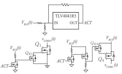
A hardware overview of that glue logic shows that it relies on discrete comparators to make sure that MOSFETs in the full-wave rectification stage are held in an off-state during startup (Fig. 3).
The downstream DC-DC converters are disabled so that they do not draw excessive current from the capacitor storage stage. They also designed a transfer window alignment (TWA) scheme for managing saturation of the current transformer’s magnetic core as a form of MPPT.
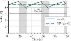
In cases of high ambient-energy availability, an energy-management module’s capacitive-storage stage may be in danger of overvoltage conditions—too much of an otherwise good thing. The management module must ensure that the voltage ratings of its supercapacitor storage unit or sensitive ICs aren’t exceeded under such high-energy harvest conditions.
Test and Evaluation of the Harvester Project
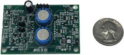
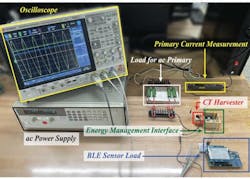
By its nature, this project is test and measurement “friendly.” The final unit (Fig. 4) was assessed via a straightforward arrangement (Fig. 5).
Among the many evaluations, they measured performance of the cold-start circuit (Fig. 6) and checked the critical “overload” function that protects against excess charging if too much energy is being harvested (Fig. 7).
The project was supported in part by the Office of Naval Research and The Grainger Foundation. The work is described in a very readable paper “Rule the Joule: An Energy Management Design Guide for Self-Powered Sensors” published in IEEE Sensors Journal.
