Inexpensive Solution Protects Sensitive Devices From Surges
>> Electronic Design Resources
.. >> Library: Article Series
.. .. >> Series: Ideas for Design
.. .. .. >> Ideas for Design Vol. 1
Download this article as a PDF file
As today’s high-tech electronic devices become smaller and faster while running at lower voltages, they also become more vulnerable to surges. Making matters worse, they often operate in harsh environments that expose them to extreme surges, particularly in industrial applications where sensors are interfaced to microcontrollers or logic devices. This idea shows engineers how to design their circuits to withstand these surges.
The key to surge protection is adding a transient voltage suppressor at the input to the sensitive devices. The simple circuitry includes a resistor and a transient suppressor that handle the voltage surge and regulate the input voltage. The tricky part is choosing the right value for the suppressor.
Properly designed, the transient suppressor appears invisible to the protected device until a surge hits. That is, during normal conditions the suppressor’s breakdown voltage, current, and capacitance will have no effect on operation and performance. When a surge strikes, the suppressor immediately clamps to a safe voltage level (the clamping voltage), conducting away the surge current.
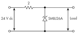
In the example circuit, the load, which can be the input of a logic device, is fed by a 24-V dc input, which can be from a sensor, transducer, or other device (Fig. 1). The source resistance is 2 Ω and the failure threshold is 36 V. The circuit uses an SMBJ26A 600-W transient voltage suppressor. If a malfunction causes a peak surge of 150 V with a duration of 10 ns at the input terminal, the suppressor must clamp that surge at 36 V or less. The current delivered by this transient is:
Ip = (150 V – 36 V)/2 Ω = 57 A (1)
The suppressor causes the surge voltage to be divided between the source impedance and itself. Equation 1 shows that the higher the clamping voltage is, the lower the surge current in the circuit. Unfortunately, the resulting current in this example would fry the circuit.
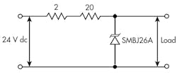
A higher-wattage suppressor could be used, but that is not advisable because the high power capacity and power dissipation would be a costly solution. Alternatively, you can add a small resistor in series with the source impedance, effectively reducing the surge current and along with it the overall size, power dissipation, and cost of the circuit (Fig. 2).
2. The addition of an inexpensive 20-Ω resistor to the input greatly reduces the surge current and power dissipated.
Assuming a small load, 10 mA, the voltage drop across the 20-Ω would be:
V20Ω = 10 mA × 20 Ω = 0.2 V (2)
Therefore, the surge current I would be:
Ip = (150 V – 36 V)/22 Ω = 5.2 A (3)
The added resistor reduces the surge current to less than 1/10 of the surge current without the resistor. The low-power suppressor can handle this current. Also, the clamping current is less than the rated current. The clamping voltage is:
From the SMBJ26A datasheet, the maximum clamping voltage, VC(max) = 42.1 V; the maximum breakdown voltage, VBR(max) = 31.9 V; and the maximum peak pulse current, Ipp(max) = 14.3 A. Using these values and the result of Equation 3 for Ip, Equation 4 yields VC = 35.5 V.
Thus the clamping voltage is a little below the threshold voltage at 25°C. For higher temperatures, de-rating parameters must be considered. The steady state power dissipated by the 20-Ω resistor is:
P20Ω = (20 mA)2 × 20 Ω = 8 mW (5)
Consequently, a 1/8-W carbon composition resistor can be used for the suppressor circuit for the given pulse condition. This small series resistor drastically improves the suppressor performance with little cost impact.


